Eureka AIR delivers breakthrough ideas for toughest innovation challenges, trusted by R&D personnel around the world.

Laser based cavity enhanced optical absorption gas analyzer

a gas analyzer and laser-based technology, applied in the field of trace gas detection, can solve the problems of inability to precisely inability to accurately estimate the coupling efficiency, and inability to accurately measure the coupling efficiency, so as to achieve the effect of improving the measurement capability

Active Publication Date: 2013-02-28
LI COR
View PDF3 Cites 15 Cited by
  • Summary
  • Abstract
  • Description
  • Claims
  • Application Information

AI Technical Summary

Benefits of technology

This patent is about a new method to detect trace gases using a special laser system. The new method is more accurate and reliable than previous methods, even when the laser and the gas are not perfectly aligned. This invention makes it easier to measure small amounts of gases in a variety of settings.

Problems solved by technology

In practice, it is difficult to precisely estimate the coupling efficiency as a lot of parameters affect it, such as spatial, polarization, and spectral overlapping of laser and cavity modes.
Moreover, this efficiency can vary over time causing a drift.
In these approaches, all fast non-correlated fluctuations of longitude and transverse intensity modes of the laser beam cause an additional, unwanted noise in the absorption measurements.
Also, slow changes of the laser and cavity mode overlapping cause an undesirable drift of the base line.

Method used


Image

  • Laser based cavity enhanced optical absorption gas analyzer
  • Laser based cavity enhanced optical absorption gas analyzer
  • Laser based cavity enhanced optical absorption gas analyzer

Examples


Embodiment Construction

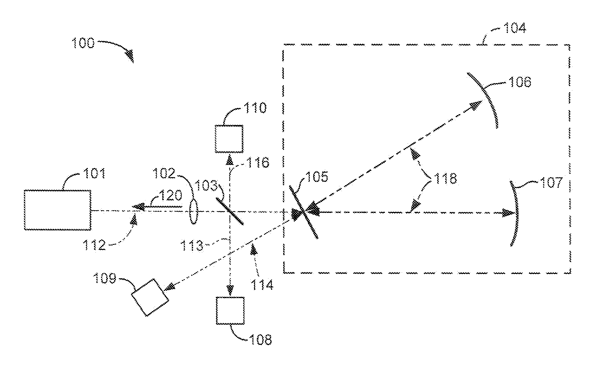
[0025]The present invention provides cavity enhanced absorption spectroscopy systems and methods for measuring trace gases with improved measurement capability that is not sensitive to laser-cavity coupling.

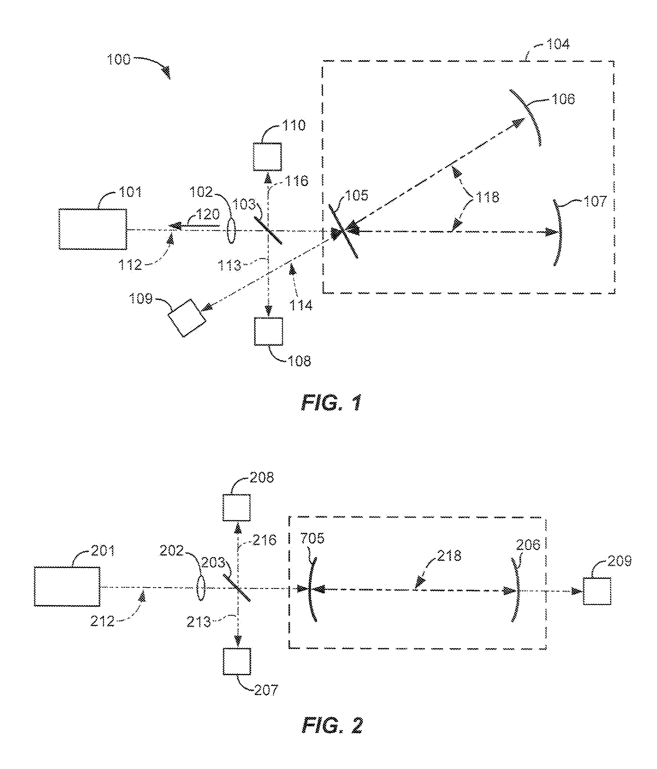
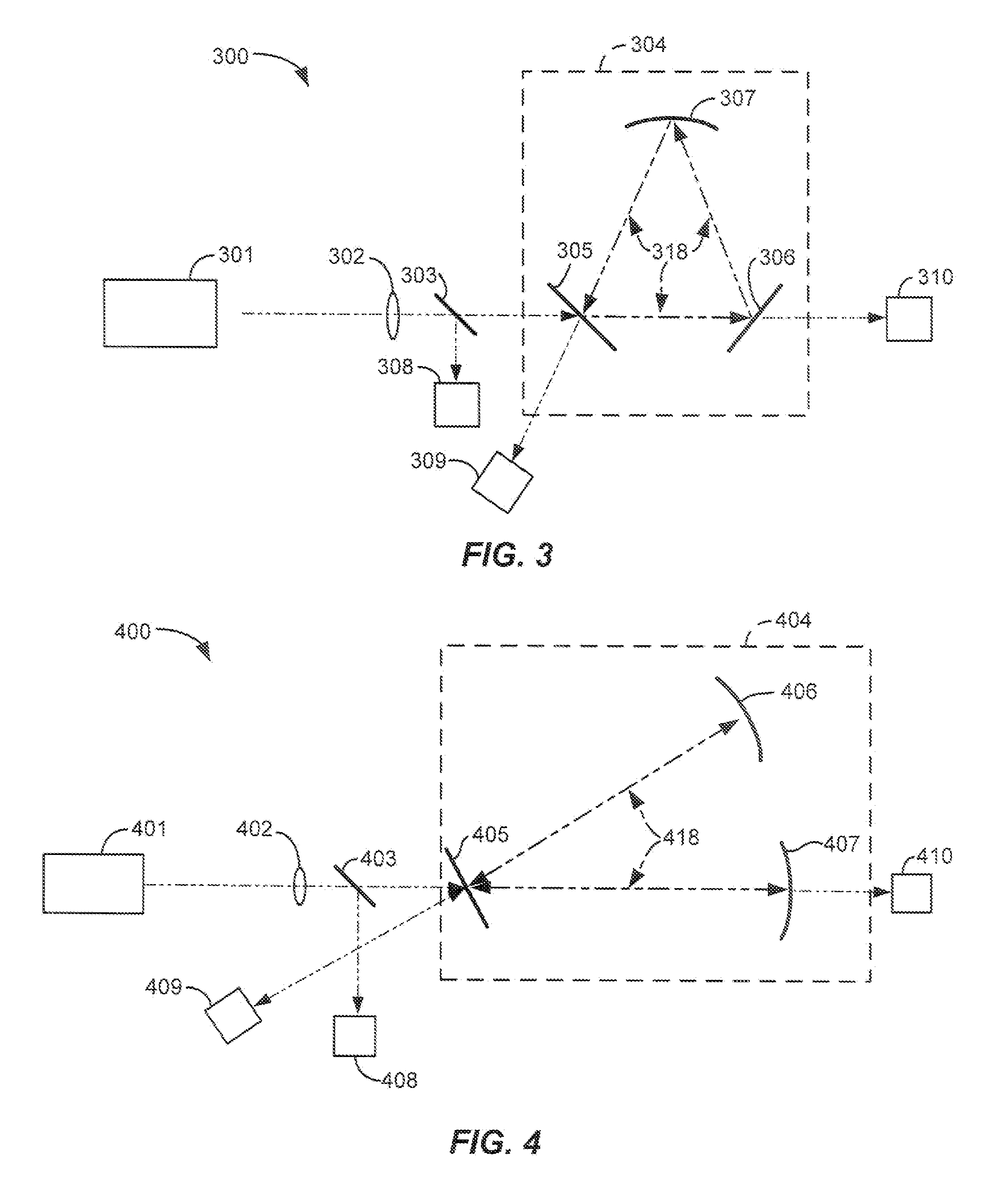
[0026]Embodiments of the present invention provide simple, precise and reliable cavity enhanced absorption spectroscopy systems and methods for detecting trace gases that has higher sensitivity, accuracy and stability as compared to existing systems and methods based upon similar principles. This is achieved by measuring three optical signals, a combination of which completely characterizes the total cavity. Embodiments of the present invention significantly simplify the baseline calibration problem, as the normalized signal only depends on total cavity loss, and not the coupling efficiency, as in traditional approaches. For example, three different exemplary configurations shown in FIGS. 1-3 are designed to allow for measuring three optical signals, which characterize the cavity...


PUM


Abstract

Cavity enhanced absorption spectroscopy systems and methods for detecting trace gases. A laser or other light source that is capable of being frequency-scanned is coupled to a resonance cavity though one of the cavity mirror. When the frequency of the laser light approaches the frequency of one of the cavity modes, the laser begins to fill the cavity to that mode. Optical intensity inside the resonance cavity reflects total cavity loss at the moment when the laser light frequency coincides with the cavity mode transmission peak. The total cavity loss is a sum of the cavity mirror losses and losses caused by absorption of a gas mixture present in the cavity. The intra-cavity optical power also depends on the coupling efficiency of the laser beam to the particular cavity mode. Measurement of intensities of three optical signals, namely, intensity of the light incident on to the cavity, intensity of the light reflected from the cavity, and intensity of the intra-cavity optical power, with their appropriate normalization advantageously significantly reduce effects of baseline calibration and drift as the normalized signal only depends on total cavity loss, and not the coupling efficiency, as in traditional approaches.

Description

BACKGROUND[0001]The present invention relates generally to generally to trace gas detection and more specifically to cavity enhanced absorption spectroscopy systems and methods for measuring the trace gases.[0002]In optical absorption spectroscopy systems and methods, optical intensity inside the resonance cavity reflects total cavity loss at the moment when the laser light frequency coincides with a cavity mode transmission peak. The total cavity loss is a sum of the cavity mirror losses and losses caused by absorption of a gas mixture present in the cavity. However, the intra-cavity optical power depends also on the coupling efficiency of the laser beam to the particular cavity mode. In practice, it is difficult to precisely estimate the coupling efficiency as a lot of parameters affect it, such as spatial, polarization, and spectral overlapping of laser and cavity modes. Moreover, this efficiency can vary over time causing a drift.[0003]In traditional cavity enhanced absorption s...

Claims


Application Information

Patent Timeline
IPC IPC(8): G01N21/59
CPCG01J3/021G01J3/42G01N21/031G01N21/39
Inventor KOULIKOV, SERGUEIKACHANOV, ALEXANDER
Owner LI COR
Why Eureka
Eureka Blog
Learn More