Electronic control device

Active Publication Date: 2013-03-07
HITACHI ASTEMO LTD
View PDF30 Cites 47 Cited by
  • Summary
  • Abstract
  • Description
  • Claims
  • Application Information

AI Technical Summary

Benefits of technology

[0006]However, in known electronic control devices such as the above-mentioned device, the plastic bus bar board tends to show a warp or deformation particularly at the time of producing the same through an insert molding. If the plastic bus bar board having such warp is set in the case without removing the warp, the intimate contact between the MOSFET (viz., heat generating element) and the flat part of the case is not obtained. In this case, the heat transmission from the MOSFET (viz., heat generating element) to the case is not effectively carried out.
[0007]Accordingly, it is an object of the present invention to provide an electronic control device that is free of the above-mentioned drawback.
[0008]In accordance with the present invention, there is provided an electronic control device which is constructed to allow a heat generating element mounted on a bus bar board (or circuit board) to exhibit a satisfied heat radiation therefrom even if the bus bar board (or circuit board) has been molded with a warp.
[0009]In accordance with a first aspect of the present invention, there is provided an electronic control device which comprises a circuit board (18) having a heat generating part (24) mounted thereon; a case (12) for installing therein the circuit board (18), the case (12) having a heat receiving portion (38) that is in contact with the heat generating part (24); at least two first is fixing units (61, 32) that are constructed and arranged to fix a peripheral portion of the circuit board (18) to the case (12); and at least one second fixing unit (62, 33) that is arranged to fix a given area (A) of the circuit board

Problems solved by technology

However, in known electronic control devices such as the above-mentioned device, the plastic bus bar board tends to show a warp or deformation particularly at the time of

Method used


Image

  • Electronic control device
  • Electronic control device
  • Electronic control device

Examples


first embodiment

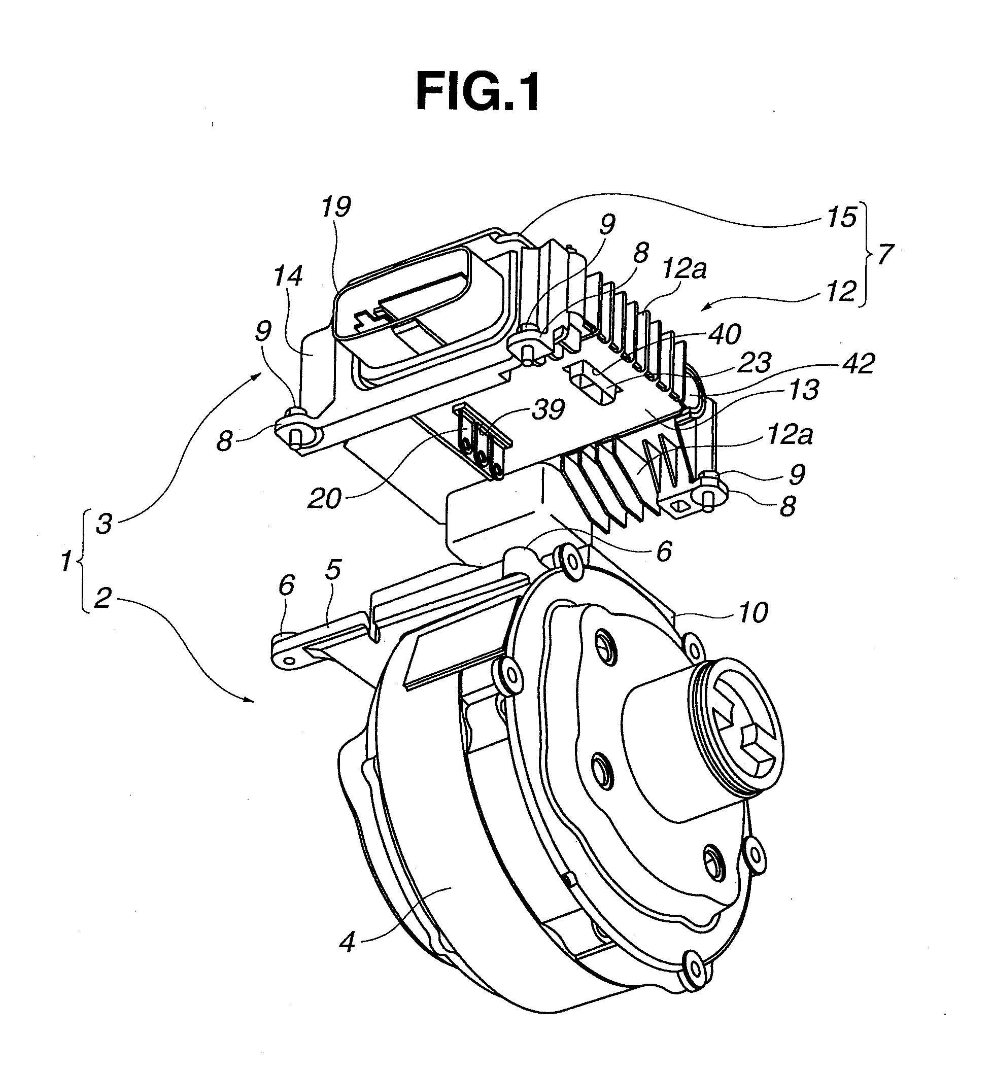
[0034]First, the present invention will be described in detail with reference to FIGS. 1 to 14.

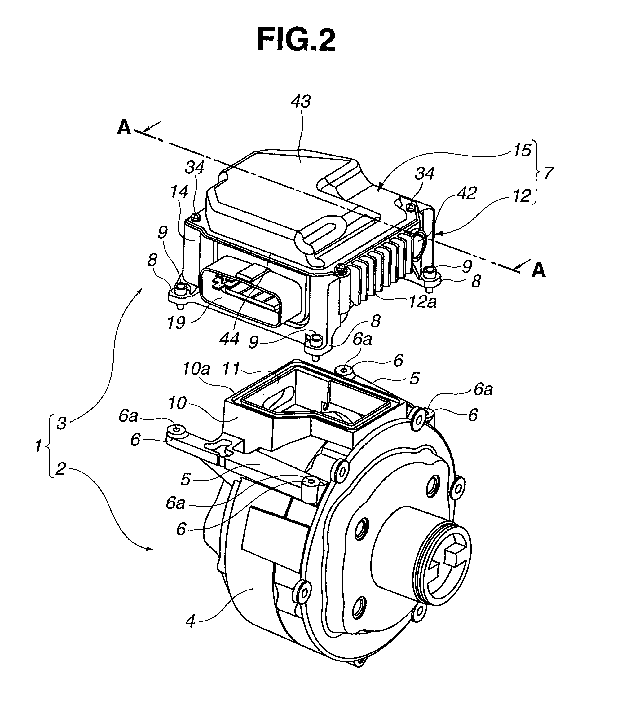
[0035]Referring to FIGS. 1 and 2, there is shown an actuator unit 1 which is used in an electric power braking device mounted on a motor vehicle.

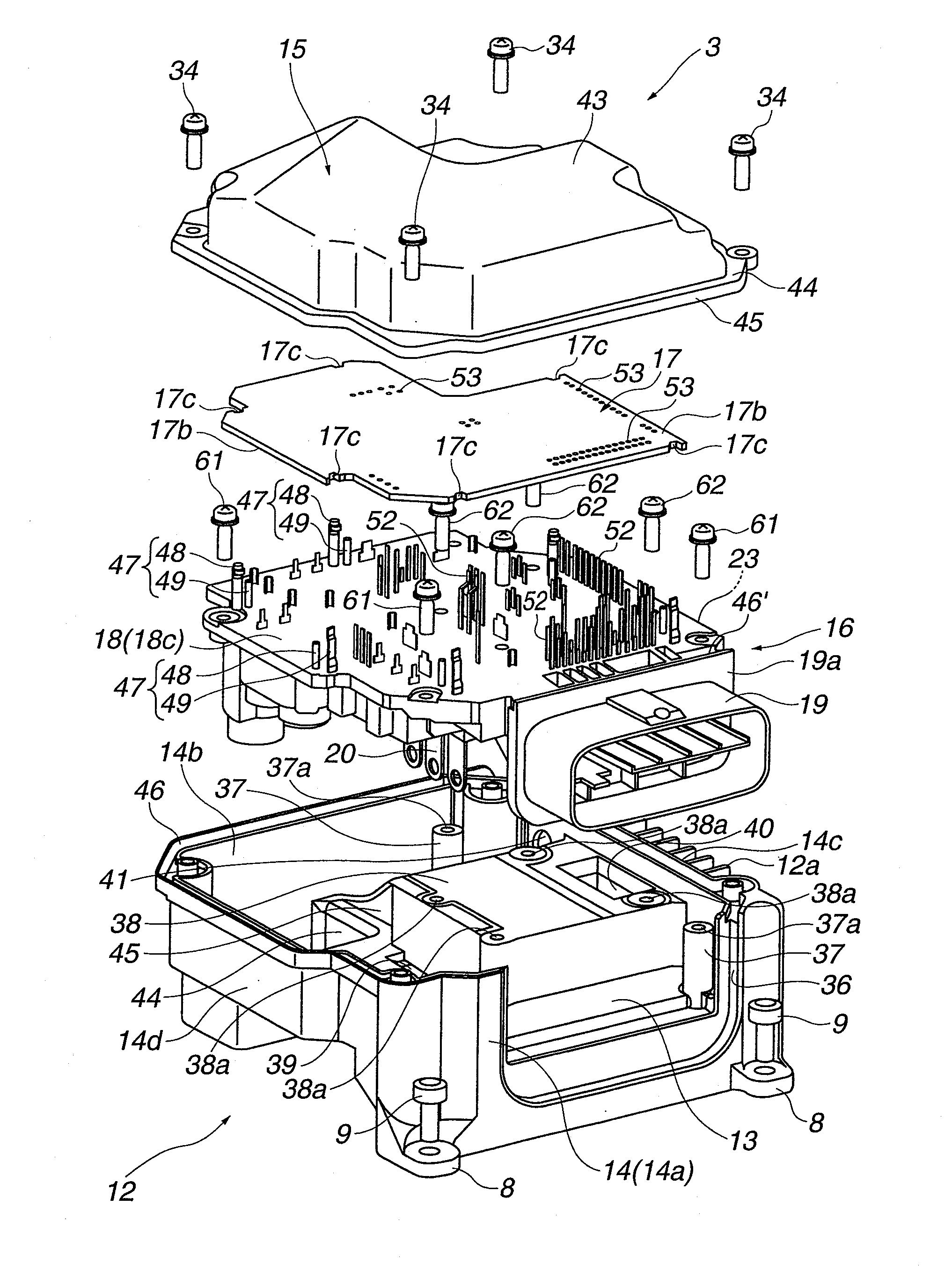
[0036]Actuator unit 1 comprises an electric motor 2 that is driven by a power of three-phase alternating current and used as an actuator for actuating a hydraulic pressure of a brake liquid and a motor control device (or electronic control device) 3 that controls operation of electric motor 2 in accordance with a brake pedal operation by a driver and an operation condition of an associated motor vehicle. Although not shown in the drawings, by the operation of electric motor 2, a ball-screw mechanism moves a piston forward and backward for controlling the hydraulic pressure of the brake liquid.

[0037]As is seen from FIG. 2, a cylindrical motor housing 4 of electric motor 2 is formed with two pedestal portions 5 that extend in an axial direction of e...

second embodiment

[0145]Referring to FIG. 15, there is shown the present invention.

[0146]As will become apparent when comparing FIG. 15 with FIG. 14 (first embodiment), the second embodiment is substantially the same as the above-mentioned first embodiment except that in the second embodiment, there is no connecting hole that corresponds to second inside connecting hole 33b provided in the first embodiment. That is, in this second embodiment, the switching element mounting zone “A” of flat base portion 18 of power module 16 is secured to raised rectangular flat portion 38 of case 12 by three inside connecting bolts 62 that are in association with three inside connecting holes 33a, 33c and 33d. If desired, third and fourth inside connecting holes 33c and 33d may be removed. In this case, securing power module 16 to case 12 is made by four outside connecting bolts 61 and one inside connecting bolt 62 that is in association with first connecting hole 33a.

third embodiment

[0147]Referring to FIG. 16, there is shown the present invention.

[0148]As is seen from the drawing, the third embodiment is substantially the same as the first embodiment except that in the third embodiment, there is no connecting hole that corresponds to first inside connecting hole 33a provided in the first embodiment. That is, in this third embodiment, the switching element mounting zone “A” of flat base portion 18 of power module 16 is secured to raised rectangular flat portion 38 of case 12 by three inside connecting bolts 62 that are in association with the three inside connecting holes 33b, 33c and 33d. If desired, third and fourth inside connecting holes 33c and 33d may be removed. In this case, securing power module 16 to case 12 is made by four outside connecting bolts 61 and one inside connecting bolt 62 that is in association with second connecting hole 33b.


PUM


Abstract

An electronic control device comprises a circuit board having a heat generating part mounted thereon; a case for installing therein the circuit board, the case having a heat receiving portion that is in contact with the heat generating part; at least two first fixing units that are constructed and arranged to fix a peripheral portion of the circuit board to the case; and at least one second fixing unit that is arranged to fix a given area of the circuit board to the case while pressing the given area against the heat receiving portion through the heat generating part, the given area being an area where the heat generating part is placed.

Description

BACKGROUND OF THE INVENTION[0001]1. Field of the Invention[0002]The present invention relates in general to an electronic control device that comprises a case in which a circuit board having a heat generating part mounted thereon is installed.[0003]2. Description of the Related Art[0004]In Japanese Laid-open Patent Application (tokkai) 2009-224708, there is disclosed an electronic control device which comprises a case that is made of a metal having a high thermal conductivity, a plastic bus bar board that is installed in the case and placed on a shelf portion defined by the case and a printed circuit board that is mounted over the bas bar board. To the bus is bar board, there is connected a MOSFET (viz., metal oxide silicon field effect transistor) through drain, gate and source terminals. As is known, the MOSFET is an electric element that generates heat when electrically energized.[0005]For promoting a heat radiation from the MOSFET to cool the same, the MOSFET is placed on a flat...

Claims


Application Information

Patent Timeline
IPC IPC(8): H05K7/20
CPCH05K5/006H05K7/20854
Inventor WATANABE, HIROFUMINAKANO, KAZUHIKOYASUKAWA, DAISUKE
Owner HITACHI ASTEMO LTD
Why Eureka
Try Eureka