
Automated Temperature Control System for Solid-Fueled Grills or Ovens

a technology of automatic temperature control and solid-fuel grills, which is applied in the direction of temperature measurement in household appliances, domestic stoves or ranges, instruments, etc., can solve the problem of relatively small electricity consumption

Active Publication Date: 2013-03-14
IOT CONTROLS LLC
View PDF10 Cites 94 Cited by
  • Summary
  • Abstract
  • Description
  • Claims
  • Application Information

AI Technical Summary

Benefits of technology

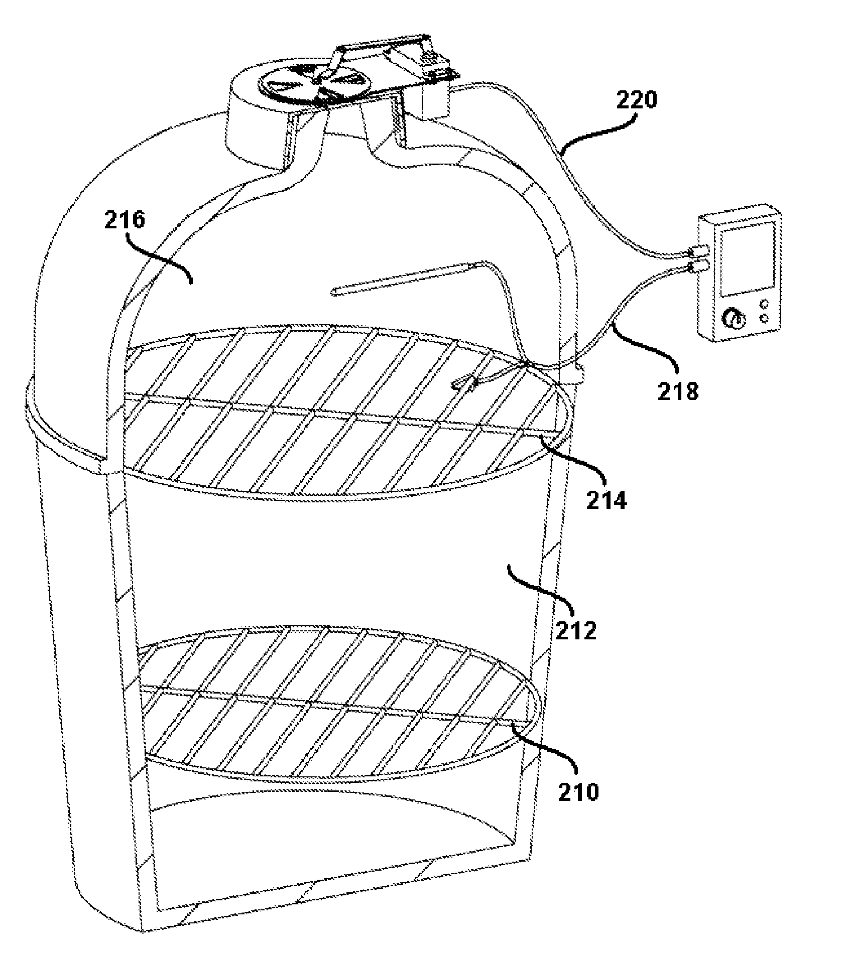
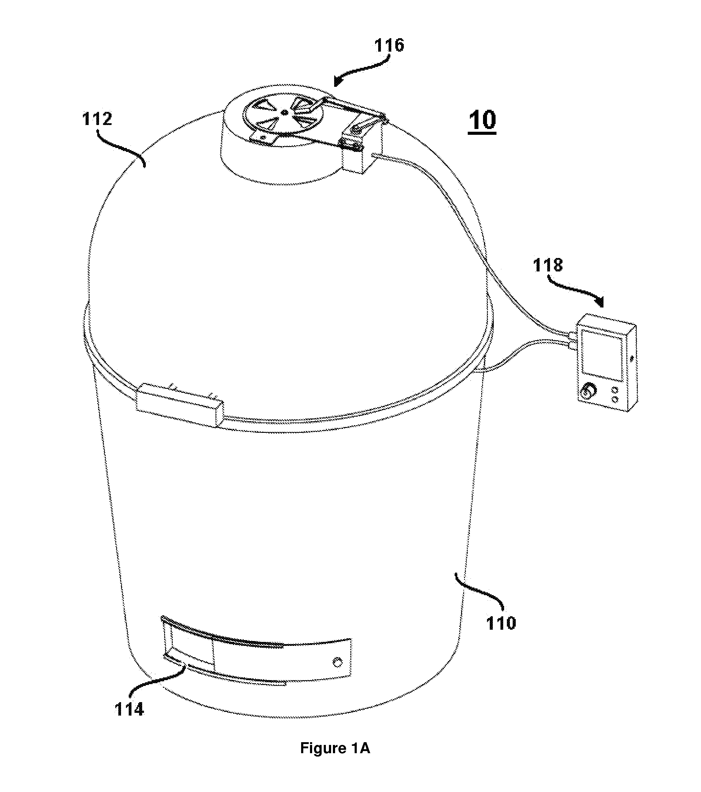
The patent describes an automated temperature control system for solid-fueled grills that uses a digital feedback device to monitor and regulate the temperature. This system eliminates the need for constant monitoring and adjusting and provides accurate temperature control across a wide range. It is quick to respond to combustion flare ups and consumes minimal electricity. The system can be easily retrofitted to existing grills or ovens and is simple to operate.

Problems solved by technology

Furthermore, the system described herein consumes relatively small amounts of electricity, is simple to operate and may easily be retrofitted to use in connection with solid-fueled grills or ovens already on the market.

Method used


Image

  • Automated Temperature Control System for Solid-Fueled Grills or Ovens
  • Automated Temperature Control System for Solid-Fueled Grills or Ovens
  • Automated Temperature Control System for Solid-Fueled Grills or Ovens

Examples


example 1

Operation of Exemplary Embodiment

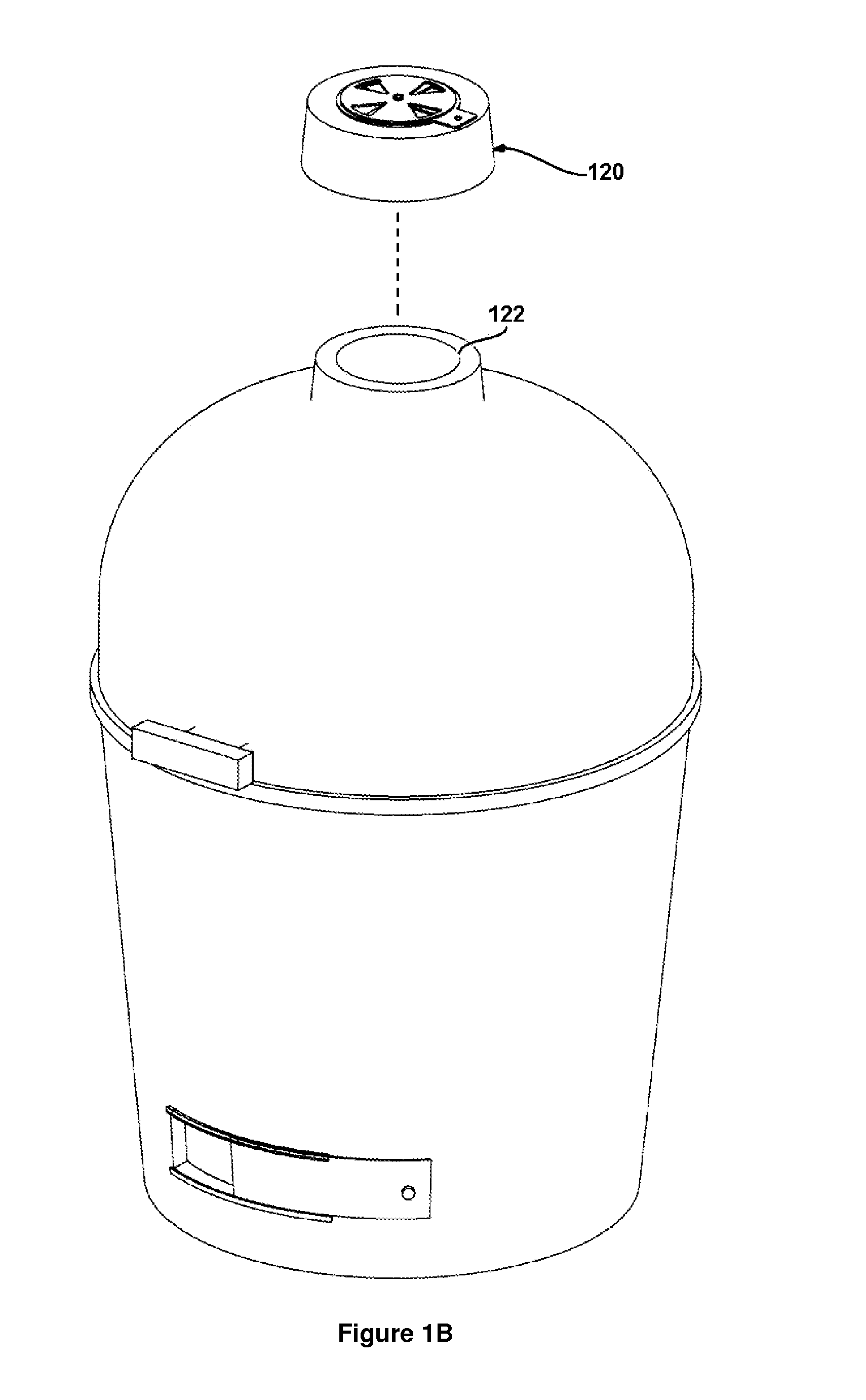
[0060]The exemplary embodiment shown in FIG. 1 depicts a grill wherein automated damper assembly 116 is disposed atop grill exhaust vent 122, with the assembly 116 held in place by gravity. Assembly 116 is installed by removing existing grill exhaust vent 120 and replacing it with assembly 116, which will be configured to adapt to the dimensions of the grill on which the assembly is installed. While this is an exemplary means of attachment for assembly 116, alternate means of attachment for further embodiments may include use of a magnetic base or other mechanical fasteners, including mounting brackets that are attached by screws or bolts. Another attachment means includes a base adapter that may be left on the grill from which the remainder of the damper unit is readily detachable. The attachment between the primary unit and the base adapter may also be screw threads, a twist / lock mechanism, interference fit, magnetic coupling, or some type of simpl...

example 2

Operation of Another Exemplary Embodiment

[0086]Operation of such an embodiment of the automated temperature control system 10 is similar to operation of the previous embodiment of the system 10, with certain distinctions to be discussed herein. Prior to the start of a cooking cycle, operating temperature probe 312 (and optionally, food temperature probe 310) are connected to temperature probe lead receptacle 1214 of wireless local control module 1105 by temperature probe leads 218. The automated temperature control system 10 is activated by powering on wireless remote control module 1010 using user interface buttons 612, and by powering on wireless automated damper assembly 1012 using power button 1116. It should be noted that the food temperature probe 310 is optional throughout this example and does not necessarily affect the operation of the system 10.

[0087]The user configures the cooking operation by interfacing with wireless remote control module 1010 in the same manner as desc...


PUM


Abstract

An automated temperature control system for a barbecue grill or other structure comprises an automated damper assembly coupled to a vent of said grill, which damper assembly opens and closes selectively to adjust the flow passage area of the grill's vent. The system further comprises an operating area temperature probe for communicating the temperature of the operating area of the grill to the automated damper assembly, such that the automated damper assembly may maintain a user-specified target operating temperature by way of affecting combustion rates within the grill. A remote control may also be provided to allow the user to input a desired temperature for the system to obtain and / or to change temperature information for the grill or other structure.

Description

FIELD[0001]This application relates to ovens, charcoal-burning barbecue grills, and the like, and more specifically, to temperature control of such ovens, grills and like devices.BACKGROUND[0002]Temperature control of solid-fueled grills is generally affected through manual throttling of a vent damper located in series with at least one of a combustion chamber inlet air vent, or combustion chamber exhaust vent. For example, during operation of a solid-fueled grill, the temperature of the grill may be reduced by at least partially closing one or more of the combustion chamber inlet or exhaust vent dampers. This action reduces the flow of fresh air for combustion to the fuel, thus resulting in a reduction of the rate of heat energy released by the combustion process. Conversely, the operating temperature of a solid-fueled grill may be increased during operation by at least partially opening one or more of the combustion chamber inlet or exhaust vent dampers.[0003]Many charcoal or wood...

Claims


Application Information

Patent Timeline
Patent Type & Authority Applications(United States)
IPC IPC(8): A47J27/00F24B1/02
CPCA47J37/0786F24B1/1895F24B1/187G01K2207/06B62D33/0273F24C15/32F24C15/2007A23L5/17A47J2202/00A47J37/0754F24C15/001B60R11/06B60R2011/004F24B5/08F24C15/322A47J37/0664
Inventor REINHART, ERIC
Owner IOT CONTROLS LLC
Learn More