Morphing segmented wind turbine and related method

Active Publication Date: 2013-03-14
THE BOARD OF TRUSTEES OF THE UNIV OF ILLINOIS +1
View PDF3 Cites 23 Cited by
  • Summary
  • Abstract
  • Description
  • Claims
  • Application Information

AI Technical Summary

Benefits of technology

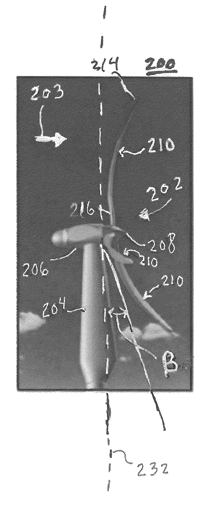
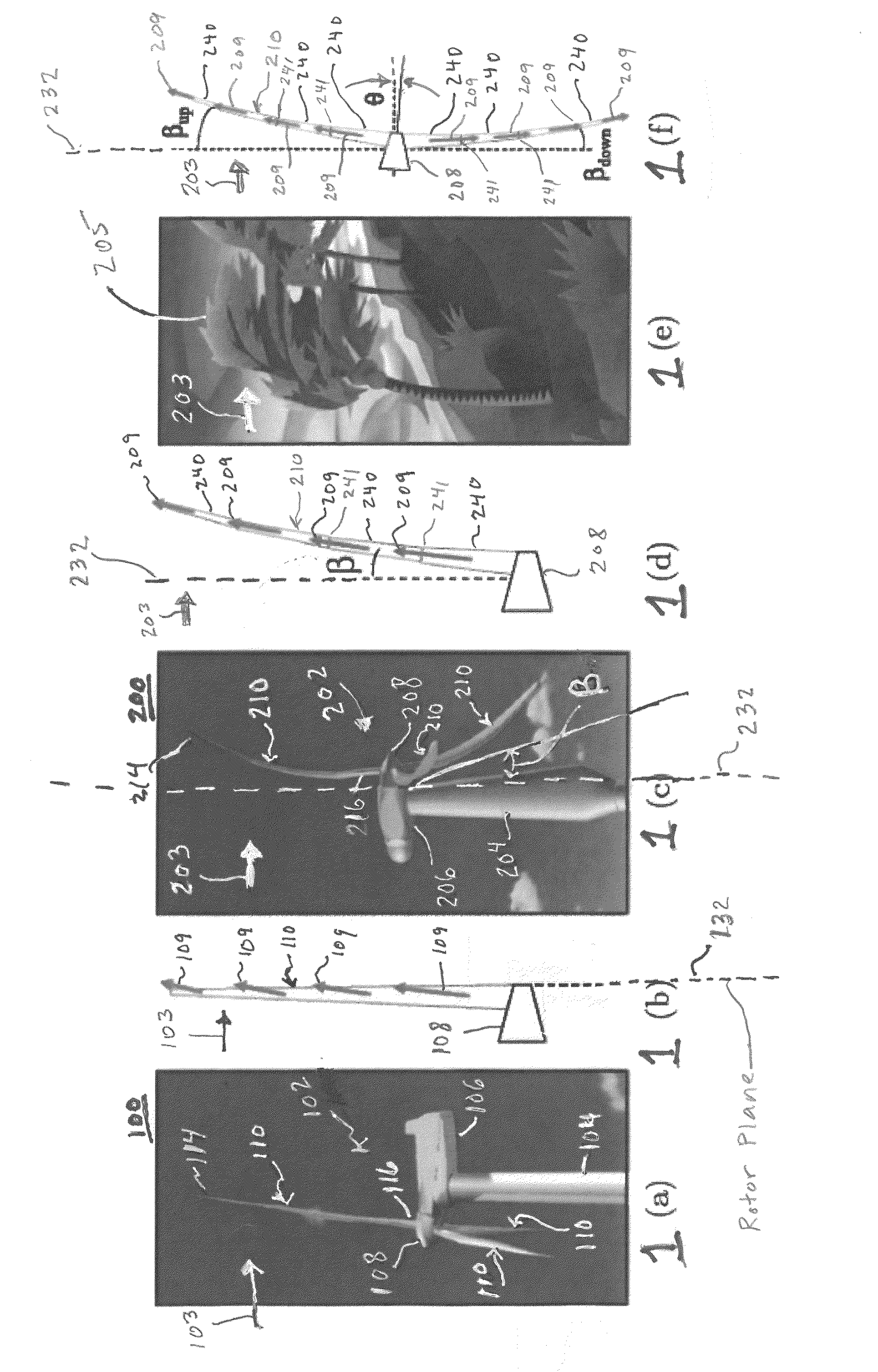
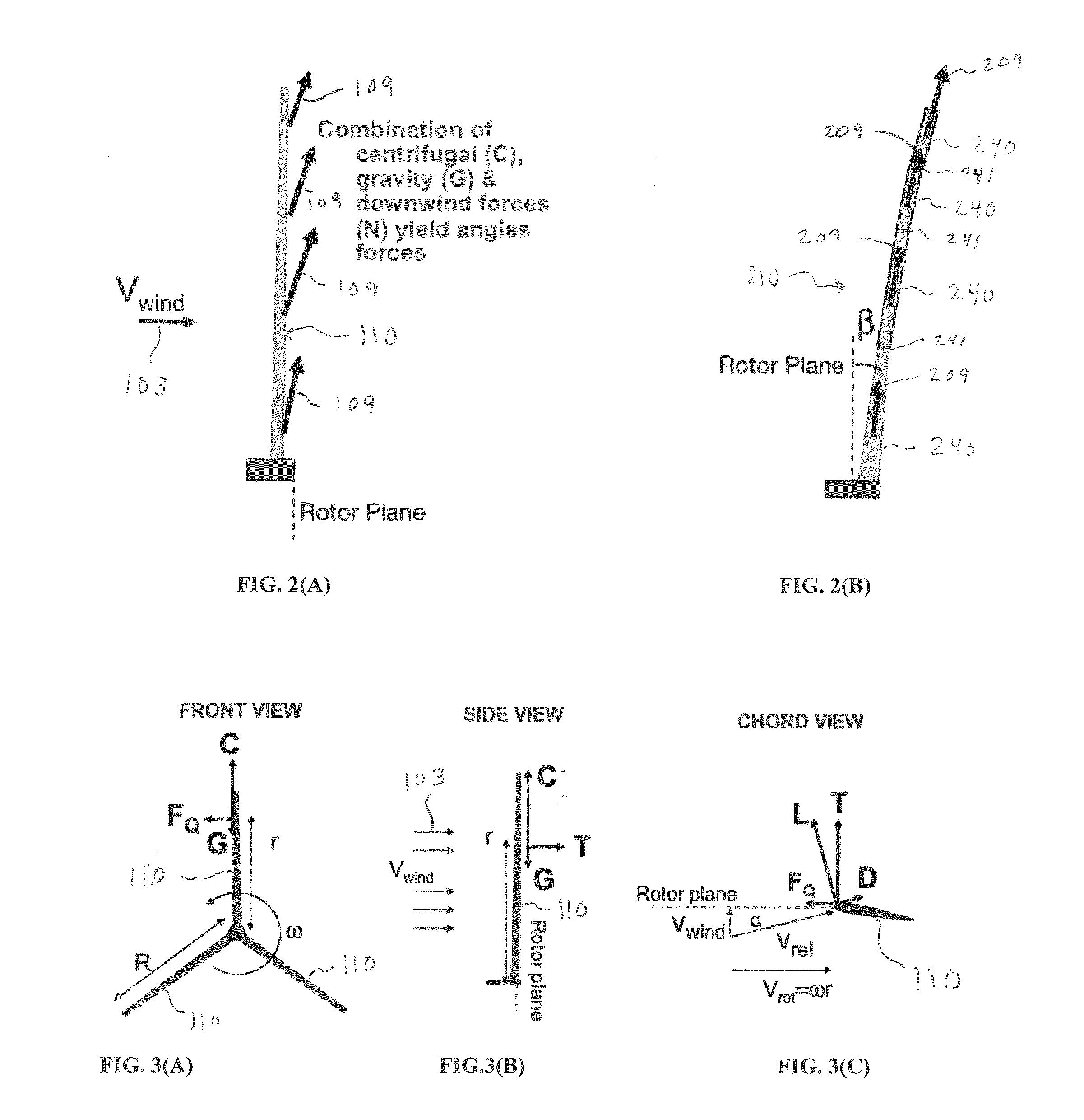
[0004]A morphing segmented concept is submitted herein as an embodiment of the present invention for future extreme-scale wind turbine systems. Both “twist morphing” and “downwind morphing” can be employed. The twist morphing pertaining to an embodiment of the present invention may be accomplished by using segmented blades connected by screw sockets and a tension cable system (as well as other available coupling mechanisms and tension control systems). At low wind and rotor speeds, the segmented blades may be, for example, fully tensioned and set at high pitch to ensure start-up and maximum power at low speeds. At high rotor rpm, the cable tension can be designed such that centrifugal forces drive the blade segments outward so as to unwind/feather the rotor and prevent over-speed. This effectively acts like a passive pitch control for rotor speeds. Perhaps more importantly, sti

Problems solved by technology

In addition, noise (and visual) production is likely to be very significant for extreme-scale systems indicating that such systems are best suited for off-shore siting.
Such siting may also reduce many existing environmental impacts but leads to complications in terms

Method used


Image

  • Morphing segmented wind turbine and related method
  • Morphing segmented wind turbine and related method
  • Morphing segmented wind turbine and related method

Examples


examples

[0065]Practice of an aspect of an embodiment (or embodiments) of the invention will be still more fully understood from the following examples and experimental results, which are presented herein for illustration only and should not be construed as limiting the invention in any way.

example set no.1

Example Set No. 1

[0066]To demonstrate reduction of structural stresses and blade mass, finite element analysis (FEA) has been conducted by the Applicants at rated power conditions for conventional vs. segmented morphing rotors. The simulated rotors employed a fiberglass shell with the aerodynamic mold lines (including airfoil shape, size, and twist as a function of rotor radius) of the NREL 5 MW reference turbine blade, but scaled (See Jonkman, J., Butterfield, S., Musial, W., Scott, G., “Definition of a 5-MW reference wind turbine for offshore system development,” NREL Technical Publishing, 2009(NREL / TP-500-38060, of which is hereby incorporated by reference herein in its entirety.) to a 10 MW system. The surface discretizations are shown in FIGS. 7(A) and 7(b). The downwind morphed geometry was determined based on a zero net moment in the downstream direction but retained the finite torque-wise (power-producing) moment about the hub axis.

[0067]The von Mises stresses for the conven...

example set no.2

Transformational Cost Reduction

[0068]The various aspects of embodiments of the present invention SUMR design directly addresses, among other things, cost of energy (COE) reduction goals for offshore or land wind turbines in a number of ways. The morphing rotor design of various embodiments of the present invention significantly reduces both of the rotor and overall turbine fatigue and extreme loads, allowing a significant mass and cost reduction both in the rotor itself and in the balance of the turbine's overall load path. The reduction in loads and tower head mass allows the reduction of mass and cost for the turbine tower and foundation system as well.

[0069]Referring to Tables, 1, 2 and 3, to illustrate the potential COE reductions possible with a next generation offshore wind turbine based on the SUMR turbine, the proposed configuration has been compared to a baseline turbine design using the NREL Wind Turbine Design Cost and Scaling Model, see Table 1. The NREL model defines a ...


PUM

PropertyMeasurementUnit
Forceaaaaaaaaaa
Angleaaaaaaaaaa
Centrifugal forceaaaaaaaaaa

Abstract

A downwind morphing rotor that exhibits bending loads that will be reduced by aligning the rotor blades with the composite forces. This reduces the net loads on the blades which therefore allow for a reduced blade mass for a given maximum stress. Also provided is a pre-aligned configuration rotor whereby the rotor geometry and orientation does not change with wind speed, and instead is fixed at a constant downwind deflection consistent with alignment at or near the rated wind speed conditions. Also provided is a twist morphing rotor where the airfoil-shapes around the spars twist relative to the wind due to aerodynamic forces so as to unload the rotors when there is a gust. This can help reduce unsteady stresses on the blade and therefore may allow for reduced blade mass and cost. The twist morphing rotor may be combined with either downwind morphing rotor or pre-alignment rotor.

Description

CROSS-REFERENCE TO RELATED APPLICATIONS[0001]The present application claims priority from U.S. Provisional Application Ser. No. 61 / 499,507, filed Jun. 21, 2011, entitled “Morphing Segmented Wind Turbine and Related Method” and U.S. Provisional Application Ser. No. 61 / 661,513, filed Jun. 19, 2012, entitled “Morphing Segmented Wind Turbine and Related Method;” the disclosures of which are hereby incorporated by reference herein in their entirety.BACKGROUND OF THE INVENTION[0002]Wind energy is a key to the nation's 2030 goals of increased energy independence and reduced environmental impact stemming from power generation (Lindenberg et al. 2008). It is projected to account for as much as 20% of U.S. power by 2030. This sustainable source will improve the nation's energy independence and allow a low environmental impact as compared to traditional fossil fuels in many ways. Firstly, it can reduce energy related emissions since the 20% wind penetration by 2030 is estimated by the U.S. Dep...

Claims


Application Information

Patent Timeline
IPC IPC(8): F03D7/04B23P15/04F03D3/06
CPCF03D1/0675F05B2240/2213Y10T29/49337F05B2240/311Y02E10/721F05B2240/302Y02E10/72
Inventor LOTH, ERICSELIG, MICHAELSTEELE, ADAM
Owner THE BOARD OF TRUSTEES OF THE UNIV OF ILLINOIS
Why Eureka
Try Eureka