Method for erecting a facility producing electrical energy from wind

a technology of wind power generation and wind power, which is applied in the direction of mechanical equipment, building repairs, machines/engines, etc., can solve the problems of reducing the efficiency of power production, the shape of the outer surface the shape of the shroud is not shaped, so as to reduce the cost of power to the user, improve power production efficiency, and reduce power loss

Active Publication Date: 2013-03-21
BAKER BROOKES H
View PDF5 Cites 12 Cited by
  • Summary
  • Abstract
  • Description
  • Claims
  • Application Information

AI Technical Summary

Benefits of technology

[0018]Another objective is to provide a method for erecting a facility that is able, by virtue of the new geographical areas available for wind power, to provide power at or near the points of demand and reduction or elimination of the need for providing additional power transmission facilities for added power production. This location also reduces power losses due to transmission over long distances, thus reducing the cost of power to the user.
[0019]Another objective is to provide a method for erecting a facility that improves power production efficiency by routing the output from turbines to a battery of generators of different sizes that can operate in different ranges of optimum efficiency over a wider range of wind velocities.
[0020]Another objective is to provide a method for erecting a facility that is able to further improve power production efficiency by combining the flow of hydraulic fluid from the two pumps in a module to one set of controls, motors and generators.
[0021]Another objective is to provide a method for erecting a facility that includes a tower support structure that greatly reduce the amount of land required for wind power production relative to conventional wind power generation facilities. This construction also allows utilization or greater wind velocities at higher elevations relative to conventional wind power generation facilities.

Problems solved by technology

However, prior art shrouds do not teach a shroud that is shaped to both increase the mass of wind passing through the shroud, and also minimize the drag on the shroud.
The shape of the shrouds, and in particular the outer surfaces of the shrouds, has a shape that will create considerable drag.

Method used


Image

  • Method for erecting a facility producing electrical energy from wind
  • Method for erecting a facility producing electrical energy from wind
  • Method for erecting a facility producing electrical energy from wind

Examples


Embodiment Construction

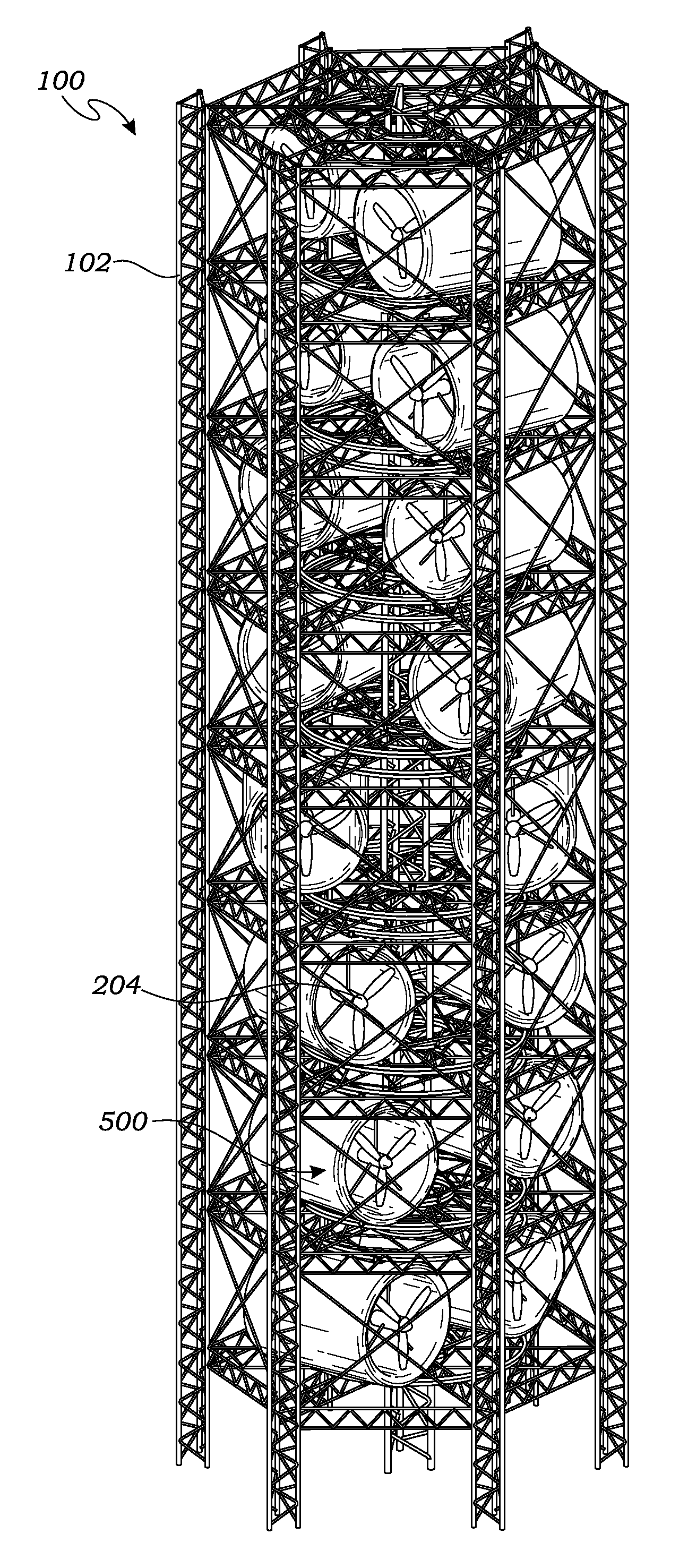
[0072]The above-described drawing figures illustrate the invention, a facility 100 for producing electrical energy from a prevailing wind above a surface.

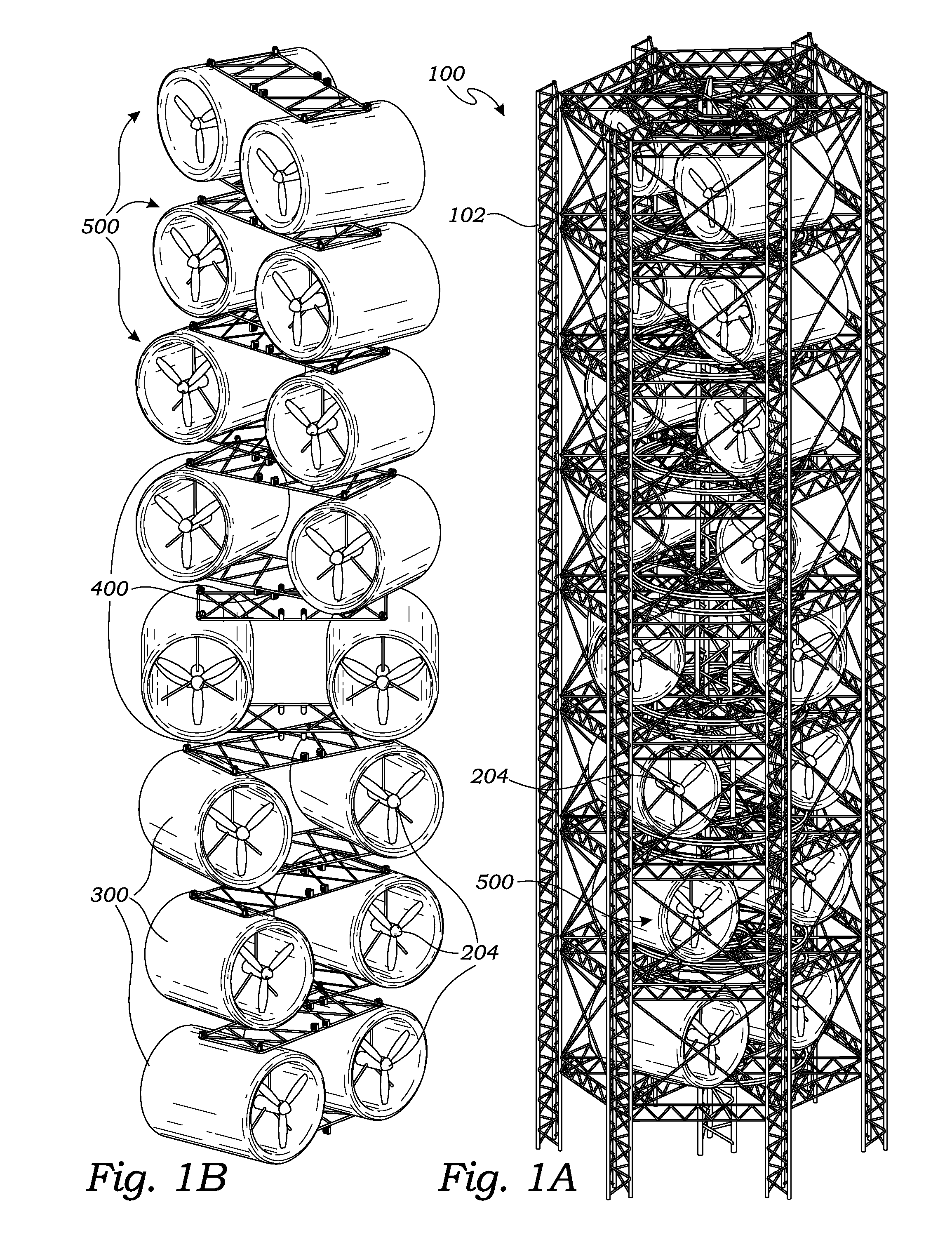
[0073]FIG. 1A is a perspective view of one embodiment of the facility 100. FIG. 1B is a perspective view of the facility 100 of FIG. 1A, with a support structure 102 removed to better illustrate multiple modules 500 of the facility 100. The embodiment, singly or in multiple installations, is most efficient in meeting large power demands where construction sites are at a premium and annual average wind speed is relatively low.

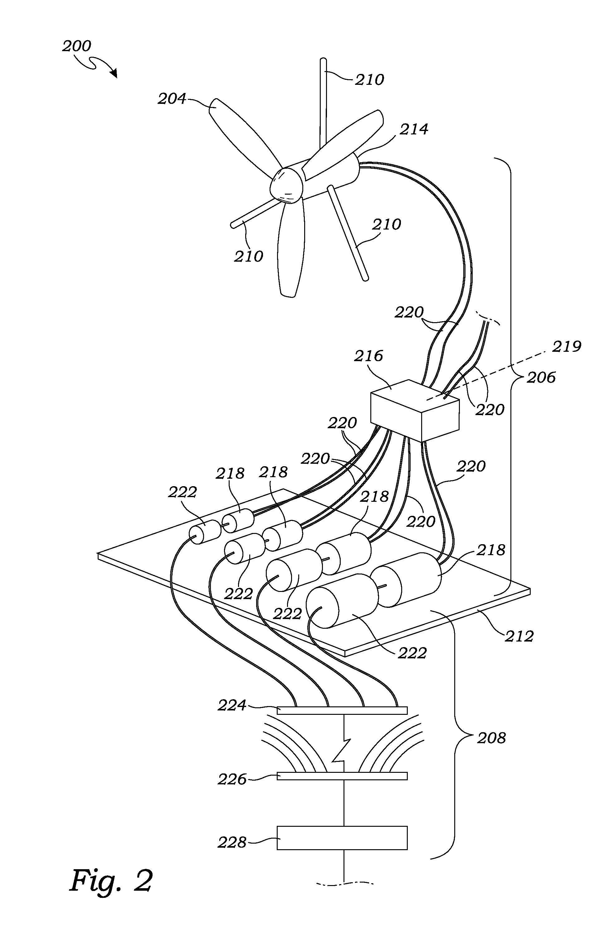
[0074]As illustrated in FIGS. 1A and 1B, the facility 100 includes a power system 200, a plurality of shrouds 300, a plurality of wind turbines 204, a plurality of modules 500, a plurality of pivotal mounting structures 400, and a support structure 102. The support structure 102 supports a large number of the wind turbines 204 far above the surface (e.g., ground, water, or other location) to both maximize the a...


PUM


Abstract

A method for erecting a facility includes the steps of constructing initial tower panels on a foundation. Work platforms and guys are installed so that additional tower panels may be installed on top of the existing tower panels. The work platforms with guys may then be raised, so that the process may be repeated until tower section height is reached. Tower sections are them completed by the addition of peripheral trusses and permanent guys, and additional tower sections are constructed by repeating the process to reach the desired facility height. Lifting units including truss and rail systems and rotatable modules with turbines in shrouds are assembled on the ground, then raised up the towers and operably mounted for generating electricity from wind. The erection process is sequenced to maintain structural integrity.

Description

CROSS-REFERENCE TO RELATED APPLICATIONS[0001]This application for a utility patent claims the benefit of U.S. Provisional Application No. 61 / 397,665, filed Jun. 15, 2010[0002]This application is a continuation-in-part of U.S. Utility application Ser. No. 13 / 161,471, filed Jun. 15, 2011, and U.S. Utility application Ser. No. 13 / 189,454, filed Jul. 22, 2011, both still pending.STATEMENT REGARDING FEDERALLY SPONSORED RESEARCH[0003]Not ApplicableBACKGROUND OF THE INVENTION[0004]1. Field of the Invention[0005]This invention relates generally to power generation devices, and more particularly to a wind power generation facility.[0006]2. Description of Related Art[0007]The prior art teaches the use of a shroud to increase the velocity of a prevailing wind in a throat of the shroud, to increase the ability of a turbine to capture energy from the wind. However, prior art shrouds do not teach a shroud that is shaped to both increase the mass of wind passing through the shroud, and also minimi...

Claims


Application Information

Patent Timeline
Patent Type & Authority Applications(United States)
IPC IPC(8): E04H12/20E04H12/34
CPCF03D1/001Y02E10/728F05B2240/40F03D1/04F03D1/02F03D9/25F03D13/10F03D13/22Y02E10/72
Inventor BAKER, BROOKES H.
Owner BAKER BROOKES H
Why Eureka
Try Eureka