Surface treatment method for copper foil, surface-treated copper foil, and copper foil for negative electrode collector of lithium ion secondary battery

a lithium ion secondary battery and surface treatment technology, applied in the direction of metallic material coating process, cell components, coatings, etc., can solve the problems of enlargement of the dimensions of the battery, difficult to coat carbon on the two surfaces of the copper foil, and insatiable applications which require a large number of charge and discharge cycles, etc., to achieve the effect of improving the electrical conductivity, and improving the surface treatment

Inactive Publication Date: 2013-03-21
FURUKAWA ELECTRIC CO LTD
View PDF0 Cites 38 Cited by
  • Summary
  • Abstract
  • Description
  • Claims
  • Application Information

AI Technical Summary

Benefits of technology

[0028]According to the present invention, there is provided a surface-treated copper foil having superior properties of: electrical conductivity, ease of surface processing for both the front and back surfaces of the metal foil, adhesion with an active material, and further ultrasonic bondability, and a surface treatment method for the above copper foil.
[0029]Further, according to the present invention, there is provided a negative electrode collector of a lithium ion secondary battery having superior properties of: electrical conductivity, ease of surface processing for both of the front and back surfaces of the metal foil, adhesion with an active material, and further ultrasonic bondability.

Problems solved by technology

However, when using carbon, the result was not satisfactory for applications which require a high capacity and a large number of charge and discharge cycles, for example, for applications for hybrid vehicles or electric vehicles.
However, it is technically difficult to coat carbon on the two surfaces of a copper foil which is used as a collector, with a uniform thickness.
Further, it suffers from the disadvantage of the enlargement of the dimensions of the battery by coating the carbon active material thick.

Method used


Image

  • Surface treatment method for copper foil, surface-treated copper foil, and copper foil for negative electrode collector of lithium ion secondary battery
  • Surface treatment method for copper foil, surface-treated copper foil, and copper foil for negative electrode collector of lithium ion secondary battery
  • Surface treatment method for copper foil, surface-treated copper foil, and copper foil for negative electrode collector of lithium ion secondary battery

Examples


first embodiment

[0040]A surface treatment method of a copper foil and a surface-treated copper foil of a first embodiment of the present invention will be explained.

[0041]Base Material

[0042]In the first embodiment of the present invention, as a base material which is to be surface treated, there is used a rolled copper foil made of copper not containing oxygen (oxygen-free copper) which is not surface treated (hereinafter, referred to as “untreated”) (hereinafter, referred to as “untreated oxygen-free rolled copper foil”).

[0043]When using the rolled copper foil made of oxygen-free copper, the ingot to be rolled to the copper foil will not contain impurities and the properties of the copper foil will not change. In particular, there is no apprehension of brittleness.

[0044]As a method of roughening the surface of the base material for use in, for example, a negative electrode collector of a lithium ion secondary battery, in order to raise adhesion with the silicon-based active material and improve bo...

example 1

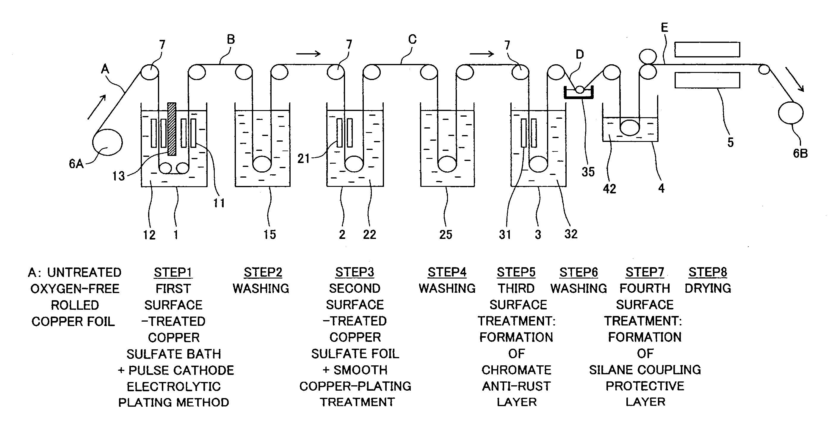
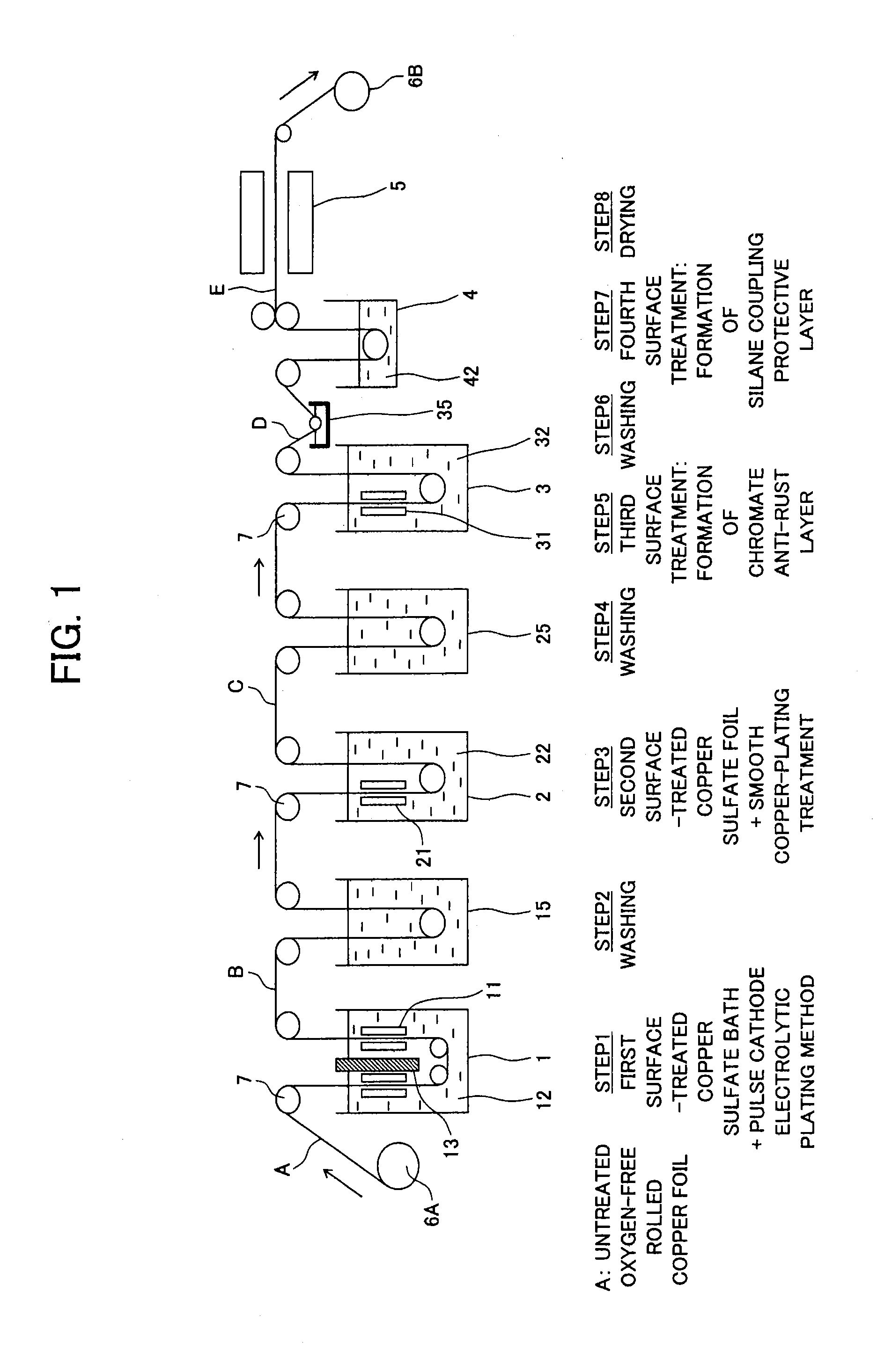
[0144]As the base material, the untreated rolled copper foil A made of an oxygen-free rolled copper A and having a thickness of 0.018 mm which has a surface roughness of 0.8 μm in terms of the surface roughness Rz defined in JIS-B-0601 and has an elongation rate at ordinary temperature (for example 25° C.) of 6.2% was used. The two surfaces of this copper foil were roughened under the following conditions.

[0145]This roughening was divided into, separated by the shield plate 13, treatment which roughens the front surface of the copper foil from the inlet of the first roughening tank 1 to the bottom side and roughening treatment for the back surface of the copper foil from the bottom to the outlet side of the tank. For the current which is supplied to the power supply contact roll 7 and iridium oxide anodes 11, the on-time was set to 10 ms and the off-time to 60 ms (sum of ratios of the on-time and off-time is 7. The copper foil A was made to move by the speed of conveyance explained ...

example 2

[0162]In Example 2, as the base material, there was used copper foil comprised of untreated rolled copper foil made of oxygen-free copper and having a thickness of 0.018 mm with a surface roughness of the two surfaces of the copper foil of 2.5 μm in terms of the surface roughness Rz defined in JIS-B-0601 and with an ordinary (atmosphere) temperature elongation rate of 6.2%.

[0163]That is, this differs from Example 1 in the surface roughness of the base material. Otherwise, the roughening was applied under the same conditions as applied in Example 1. The roughening and surface treatment were carried out so that the surface roughness of the second copper-plating layers became 3.0 μm or less in terms of the surface roughness Rz. Similar evaluation and measurement as those in Example 1 were carried out.

[0164]The results are shown in Table 3.


PUM

PropertyMeasurementUnit
surface roughnessaaaaaaaaaa
elongation rateaaaaaaaaaa
surface roughness Rzaaaaaaaaaa

Abstract

Disclosed is a copper foil for a negative electrode collector capable of simultaneously achieving high capacity and long life charge / discharge cycles in a secondary battery, wherein the front and back surfaces are of a uniform shape and, for example, the properties of a silicon active material of a lithium ion secondary battery are sufficiently realized; and a negative electrode using the copper foil. In one embodiment, a first roughened layer of metallic copper is formed by pulse cathode electrolysis roughening treatment on the surface of an untreated rolled copper foil base material of oxygen-free copper in a first roughening treatment tank (1) filled with a copper-sulphuric acid electrolyte (12), and a second copper-plate layer is formed on the surface of the first roughened layer by smooth copper plating treatment in a second copper plating treatment tank (2) filled with a copper-sulphuric acid electrolyte (22).

Description

TECHNICAL FIELD[0001]The present invention relates to a surface treatment method for a copper foil, a surface-treated copper foil, and a copper foil for a negative electrode collector of a lithium ion secondary battery which uses the surface-treated copper foil.BACKGROUND ART[0002]In a lithium ion secondary battery, in the same way as a positive electrode, the properties of a negative electrode affect the quality of the charging and discharging characteristic and of maintenance of high potential as a secondary battery.[0003]When considering the negative electrode, particularly the negative electrode collector into account, for increasing the capacity of a lithium ion secondary battery, improvement of the collection capacity of the negative electrode collector is necessary.[0004]A negative electrode collector for a lithium ion secondary battery has been produced by, for example, coating carbon (graphite) which has been mixed with a binder as an active material on the two surfaces of ...

Claims


Application Information

Patent Timeline
Patent Type & Authority Applications(United States)
IPC IPC(8): C25D7/00C25D5/18H01M4/36H01M4/66C25D5/22
CPCC23C30/00C25D5/34C25D7/0628H01M4/0452H01M4/134C25D5/48H01M4/661H01M4/667Y02E60/122C25D3/38H01M4/1395Y02E60/10C23F11/00C25D7/06H01M4/66
Inventor OGURO, RYOICHI
Owner FURUKAWA ELECTRIC CO LTD
Why Eureka
Try Eureka