Method for heat-treating silicon wafer

a technology of silicon wafers and heat-treating sheets, which is applied in the direction of lighting and heating apparatus, charge manipulation, furniture, etc., can solve the problems of high cost, reduced growth rate, and possible slip dislocation, so as to improve the in-plane uniformity in bmd size, improve the in-plane uniformity, and reduce the cop

Inactive Publication Date: 2013-03-28
GLOBALWAFERS JAPAN
View PDF11 Cites 4 Cited by
  • Summary
  • Abstract
  • Description
  • Claims
  • Application Information

AI Technical Summary

Benefits of technology

[0020]According to the present invention, the method for heat-treating the silicon wafer which can improve the in-plane uniformity in the BMD density along a diameter of the bulk of the wafer grown by the CZ process is provided. Further, the method for heat-treating the silicon wafer which can also improve the in-plane uniformity in BMD size and can reduce COP at the surface layer of the wafer is provided.

Problems solved by technology

Thus, there is a problem that a slip dislocation may take place originating from this portion in a later semiconductor-device forming heat treatment etc.
However, there is a problem that such control needs to finely control a crystal heat history of a hot zone etc., a growth rate, etc., leading to very high costs.
H8-330316, there is a problem that the crystal growth rate is decreased to reduce the productivity and lead to high costs, and BMD hardly precipitates in the bulk to reduce the strength of the wafer.
Further, even in the case where the crystal growth rate is increased while controlling the crystal heat history of the hot zone etc. precisely to increase the growth rate and move the above-mentioned OSF ring outwardly, and a V-rich region where a lot of COP's are taken in is formed uniformly along a diameter direction of the wafer, there is a limit to convection control (controlling a number of revolutions of a quartz crucible, furnace pressure, heater temperature, etc.) of a melt at the time of growing the single crystal, thus leading to a further limit to controlling the BMD density in the diameter direction of the wafer uniformly.

Method used


Image

  • Method for heat-treating silicon wafer
  • Method for heat-treating silicon wafer
  • Method for heat-treating silicon wafer

Examples


examples

[0130]Hereinafter, the present invention will be described more particularly with reference to Examples; however, the following Examples should not be construed as limiting the present invention.

experiment 1

(Experiment 1)

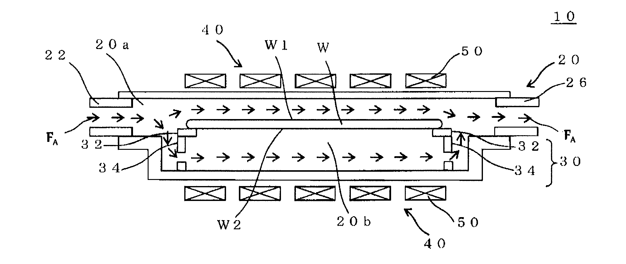
[0131]By way of the CZ process, a silicon single crystal ingot was grown by controlling a V / G ratio (V: pull rate, G: average of temperature gradients in a crystal in the direction of a raising axis in a temperature range from melting point of silicon to 1300° C.). A lot of vacancies (COP) were taken in the ingot to have a V-rich region and an OSF ring was generated, when sliced, at a part within a plane of the wafer. The silicon wafer (with a diameter of 300 mm, a thickness of 775 μm, and an oxygen concentration of 1.2×10¹⁸ to 1.3×10¹⁸ atoms / cm3) which was sliced from the above-mentioned region and in which both its sides were mirror polished was placed in a reaction space, which was held at 400° C., of a known RTP apparatus. Then, with a temperature sequence as shown in FIG. 7, a first heat treatment was performed in a gas (flow rate: 20 slm) atmosphere of 100% oxygen such that the wafer was heated at a heating rate of 50° C. / second for a retention time of 15 seconds...

experiment 2

(Experiment 2)

[0143]The maximum target temperatures in the above-mentioned first heat treatment were set as 1325° C., 1350° C., and 1380° C., and the cooling rate was set as 50° C. / second. Further, by varying the second maximum target temperature, the second heat treatment was performed under the same conditions as those in Examination 1 except for the varied temperatures.

[0144]Next, similar to Experiment 1, as for the wafer subjected to the above-mentioned second heat treatment, the number of defects at the surface layer in a region of from the surface of the wafer subjected to the above-mentioned second heat treatment to a depth of 5 μm was evaluated using the LSTD scanner MO601 manufactured by Raytex Corporation to calculate the defect density.

[0145]Furthermore, by means of the X-ray topography (XRT300, manufactured by Rigaku Corporation), a length of a slip was evaluated which was generated at the back of the wafer subjected to the above-mentioned second heat treatment.

[0146]Tab...


PUM

PropertyMeasurementUnit
temperatureaaaaaaaaaa

Abstract

A method for heat-treating a silicon wafer is provided in which in-plane uniformity in BMD density along a diameter of a bulk of the wafer grown by the CZ process can be improved. Further, a method for heat-treating a silicon wafer is provided in which in-plane uniformity in BMD size can also be improved and COP of a surface layer of the wafer can be reduced. The method includes a step of a first heat treatment in which the CZ silicon wafer is heated to a temperature from 1325 to 1400° C. in an oxidizing gas atmosphere, held at the temperature, and then cooled at a cooling rate of from 50 to 250° C./second, and a step of a second heat treatment in which the wafer is heated to a temperature from 900 to 1200° C. in a non-oxidizing gas atmosphere, held at the temperature, and then cooled.

Description

BACKGROUND OF THE INVENTION[0001]1. Field of the Invention[0002]The present invention relates to a method for heat-treating a silicon wafer (hereinafter simply referred to as wafer) sliced from a silicon single crystal ingot grown by Czochralski process (hereinafter referred to as the CZ process).[0003]2. Description of the Related Art[0004]Recent highly-integrated semiconductor devices require a severer quality of a silicon wafer used as a substrate for such semiconductor devices. In addition to reduction in density of defects such as COP in a surface layer (for example, depth region from the surface to a depth of 7 μm) which serves as a semiconductor device formation region, there is a need for improvement in wafer resistance to heat treatment where stress is high.[0005]As a method for reducing COP, Japanese Patent Application Publication (KOKAI) No. H6-295912 discloses a technology in which a silicon wafer is subjected to a heat treatment at a heat-treatment temperature of 1100 t...

Claims


Application Information

Patent Timeline
Patent Type & Authority Applications(United States)
IPC IPC(8): F27D3/00
CPCH01L21/67115H01L21/3225
Inventor SENDA, TAKESHIARAKI, KOJIAOKI, TATSUHIKOSUDO, HARUOMAEDA, SUSUMU
Owner GLOBALWAFERS JAPAN
Why Eureka
Try Eureka