

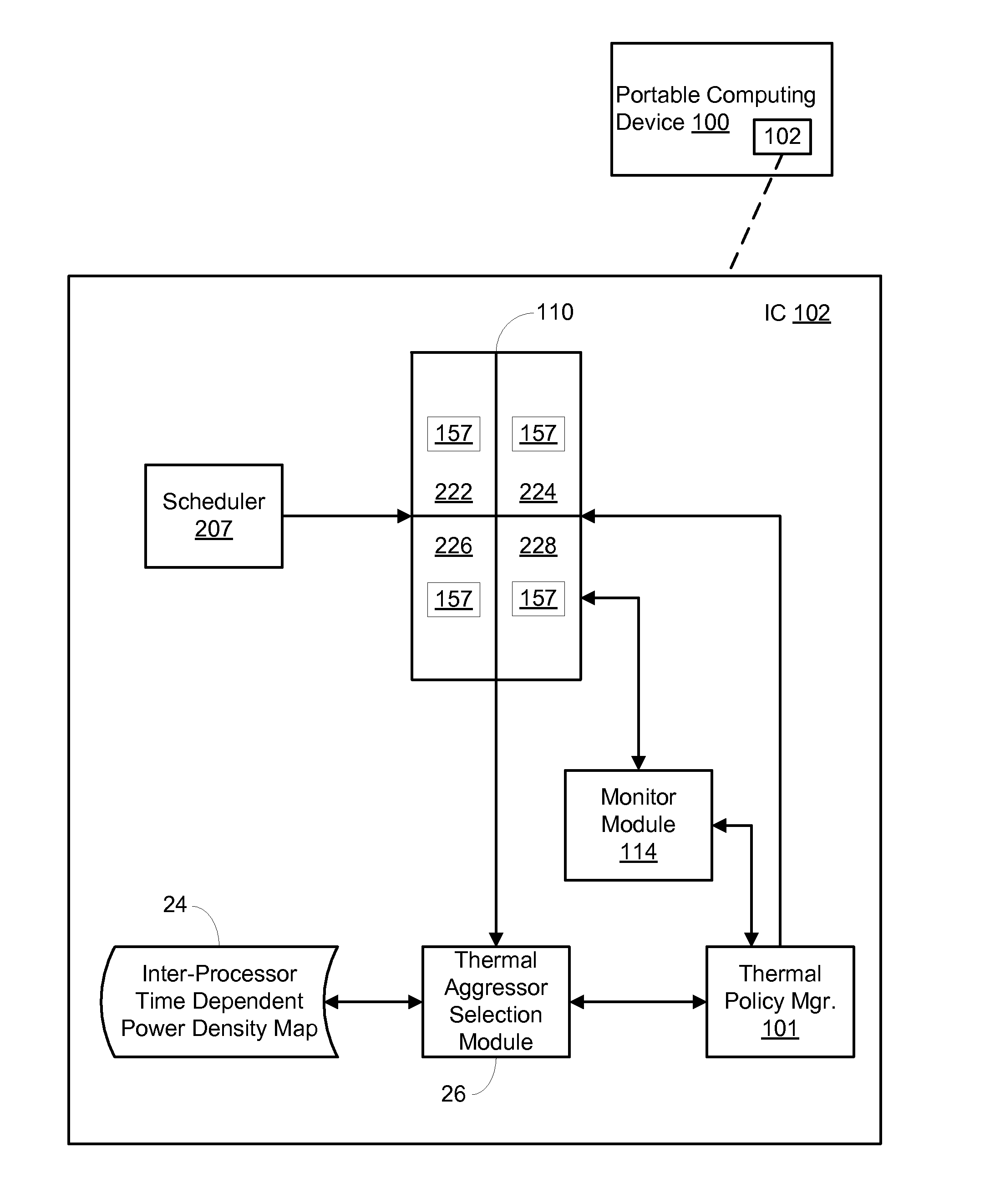
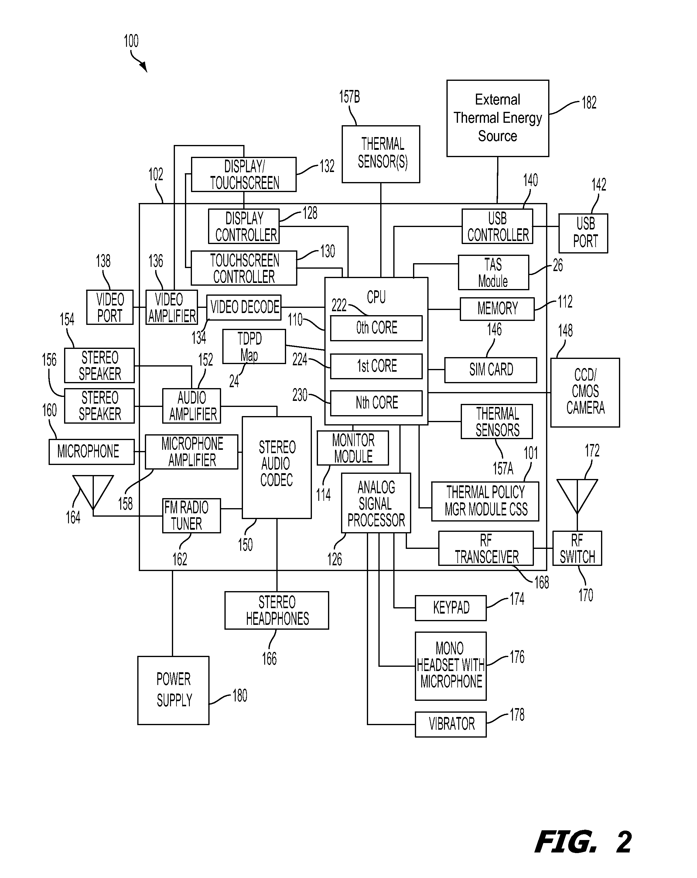
On-chip thermal management techniques using inter-processor time dependent power density data for indentification of thermal aggressors
a technology of power density and on-chip thermal management, applied in the direction of electric devices, process and machine control, instruments, etc., can solve the problems of unnecessarily affecting user experience, the application of thermal mitigation techniques to the core primarily associated with the given sensor may yield minimal benefits
- Summary
- Abstract
- Description
- Claims
- Application Information
AI Technical Summary
Benefits of technology
Problems solved by technology
Method used
Image

Examples
Embodiment Construction
[0019]The word “exemplary” is used herein to mean “serving as an example, instance, or illustration.” Any aspect described herein as “exemplary” is not necessarily to be construed as exclusive, preferred or advantageous over other aspects.
[0020]In this description, the term “application” may also include files having executable content, such as: object code, scripts, byte code, markup language files, and patches. In addition, an “application” referred to herein, may also include files that are not executable in nature, such as documents that may need to be opened or other data files that need to be accessed.
[0021]As used in this description, the terms “component,”“database,”“module,”“system,”“thermal energy generating component,”“processing component” and the like are intended to refer to a computer-related entity, either hardware, firmware, a combination of hardware and software, software, or software in execution. For example, a component may be, but is not limited to being, a pro...
PUM
 Abstract
Description
Claims
Application Information