Imaging apparatus, imaging system, and method for controlling imaging apparatus

a technology of imaging apparatus and imaging system, applied in the direction of radioation controlled devices, television systems, instruments, etc., can solve the problems of affecting usability and capturing the charge generated by radiation or light applied in the preceding imaging operation

Active Publication Date: 2013-04-04
CANON KK
View PDF0 Cites 9 Cited by
  • Summary
  • Abstract
  • Description
  • Claims
  • Application Information

AI Technical Summary

Benefits of technology

[0009]An imaging apparatus according to embodiments of the present invention is an imaging apparatus including a detector including a plurality of conversion elements each having a first electrode, a second electrode, and a semiconductor layer disposed between the first electrode and the second electrode and converting radiation or light into charge, the detector performing an imaging operation of outputting an electrical signal based on the charge; a power supply unit that supplies a first voltage to the conversion elements for enabling the conversion elements to convert the radiation or light into the electric charge in the imaging operation to the conversion elements; and a control unit that controls the detector and the power supply unit, wherein the control uni...

Problems solved by technology

When imaging is performed a plurality of times, charge generated by radiation or light applied in the preceding imaging operation may be trapped in the trap level.
The afterimage may be prevented by extending the ti...

Method used


Image

  • Imaging apparatus, imaging system, and method for controlling imaging apparatus
  • Imaging apparatus, imaging system, and method for controlling imaging apparatus
  • Imaging apparatus, imaging system, and method for controlling imaging apparatus

Examples


first embodiment

[0030

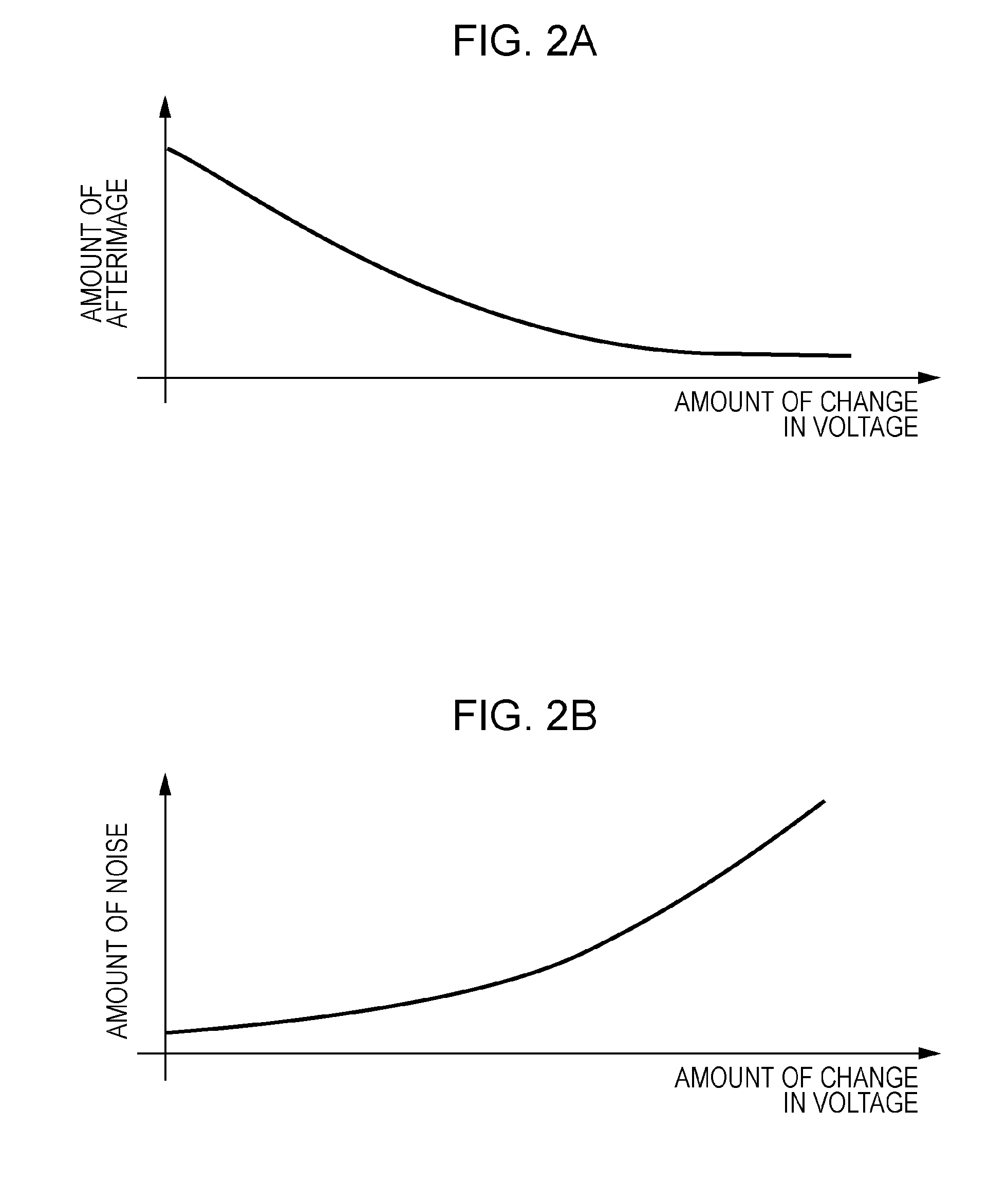
[0031]First, in order to explain the concept of the present invention, the characteristics on the amount of afterimage of a conversion element according to a first embodiment of the present invention and a characteristic of the amount of noise will be described with FIGS. 2A and 2B, respectively.

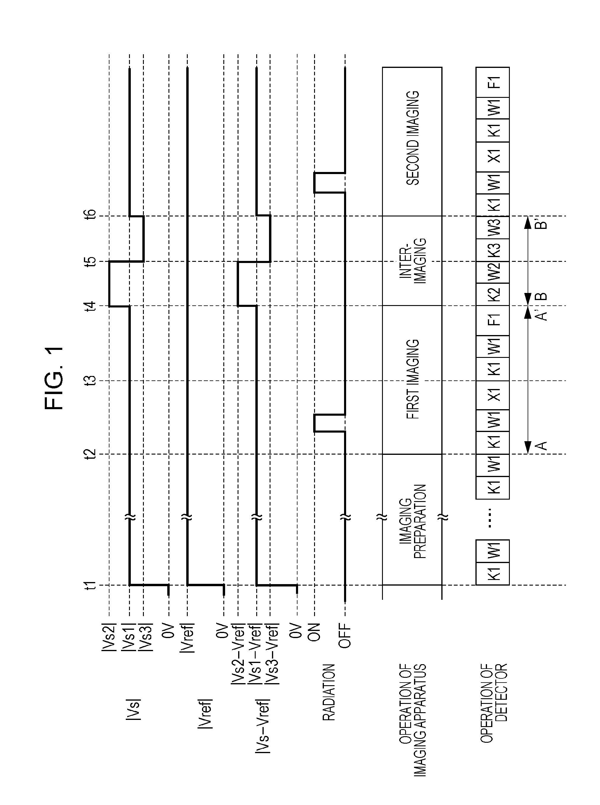
[0032]The conversion element has a semiconductor layer between two facing electrodes, and is capable of converting radiation or light into charge by supplying a voltage between the two electrodes. Here, the voltage to be supplied between the two electrodes of the conversion element is a voltage to be supplied to the conversion element. In an imaging operation including a period during which radiation or light is applied, a voltage (hereinafter referred to as the first voltage) for depleting the semiconductor layer is supplied between the two electrodes as the voltage to be supplied to the conversion element. Thus, the conversion element is able to convert radiation or light into charge....

second embodiment

[0055

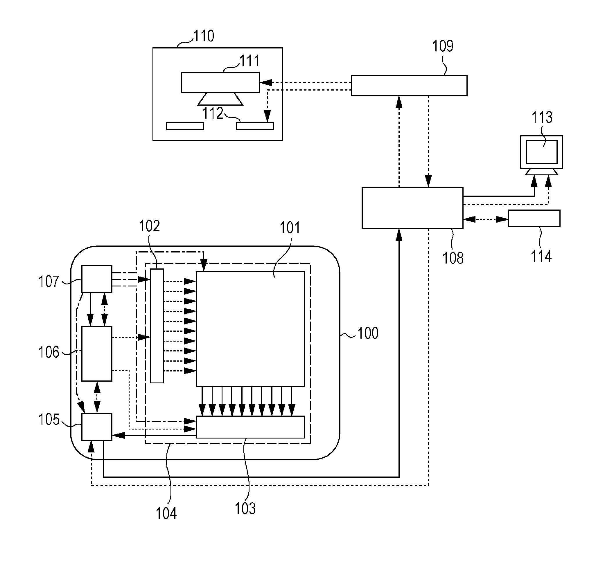
[0056]Next, an imaging apparatus according to a second embodiment of the present invention will be described with reference to FIGS. 6A and 6B. The same configurations as those according to the first embodiment described with reference to FIG. 3 are assigned the same numerals and the detailed description thereof is omitted. FIG. 6B illustrates a schematic equivalent circuit of one pixel.

[0057]While in the detection unit 101 according to the first embodiment, a PIN photodiode is used for each of the conversion elements 201, in a detection unit 101′ according to this embodiment, an MIS photoelectric conversion element is used for each of conversion elements 501 as an MIS conversion element. In addition, in the first embodiment, the other electrodes of the conversion elements 201 are electrically connected to the first power supply 107a via the common bias line Bs. In this embodiment, in contrast, the other electrodes of conversion elements 501 are electrically connected to a firs...


PUM


Abstract

An imaging apparatus includes a detector having a plurality of conversion elements for converting radiation or light into an electric charge, a power supply unit that supplies a first voltage to the conversion element in a first imaging operation, and a control unit that controls the detector and the power supply unit. During a period between the first imaging operation and a second imaging operation, the control unit controls to perform a first inter-imaging operation in which a second voltage different from the first voltage is supplied to the conversion element, and, subsequently to the first inter-imaging operation, a second inter-imaging operation in which a third voltage different from the first and the second voltages is supplied to the conversion element. The absolute value of the difference between the third and the first voltages is smaller than the absolute value of the difference between the second and the first voltages.

Description

TECHNICAL FIELD[0001]The present invention relates to an imaging apparatus and an imaging system, and a method for controlling the same. More specifically, the present invention relates to a radiation imaging apparatus and a radiation imaging system, and a method for controlling the same, which are suitable for use in still image radiography such as general imaging in medical diagnosis or moving image radiography such as fluoroscopic imaging.BACKGROUND ART[0002]In recent years, radiation imaging apparatuses using a flat panel detector (FPD) formed of semiconductor materials have been put into practical use as imaging apparatuses to be used for X-ray based medical imaging diagnosis or non-destructive testing. Hereinafter, flat panel detectors will be generally referred to as “detectors”. In, for example, medical imaging diagnosis, such radiation imaging apparatuses have been used as digital imaging apparatuses for still image radiography such as general imaging or moving image radiog...

Claims


Application Information

Patent Timeline
IPC IPC(8): H01L27/146G01T1/24
CPCH04N5/32G01T1/247H04N5/3205H04N5/321H04N5/374A61B6/487A61B6/00H04N5/359A61B6/4233H04N25/62H04N25/76
Inventor SUGAWARA, ERIKOKAMESHIMA, TOSHIOYAGI, TOMOYUKITAKENAKA, KATSUROSATO, SHOIWASHITA, ATSUSHIOKADA, HIDEYUKI
Owner CANON KK
Why Eureka
Try Eureka