System for Absorbing and Distributing Side Impact Energy Utilizing an Integrated Battery Pack and Side Sill Assembly

a technology of side impact energy and side sill, which is applied in the direction of electric propulsion mounting, roofs, transportation and packaging, etc., can solve the problems of significant increase in vehicle weight, limited protection, and particularly challenging side impact collisions for vehicle safety engineers

Active Publication Date: 2013-04-11
TESLA INC
View PDF40 Cites 76 Cited by
  • Summary
  • Abstract
  • Description
  • Claims
  • Application Information

AI Technical Summary

Benefits of technology

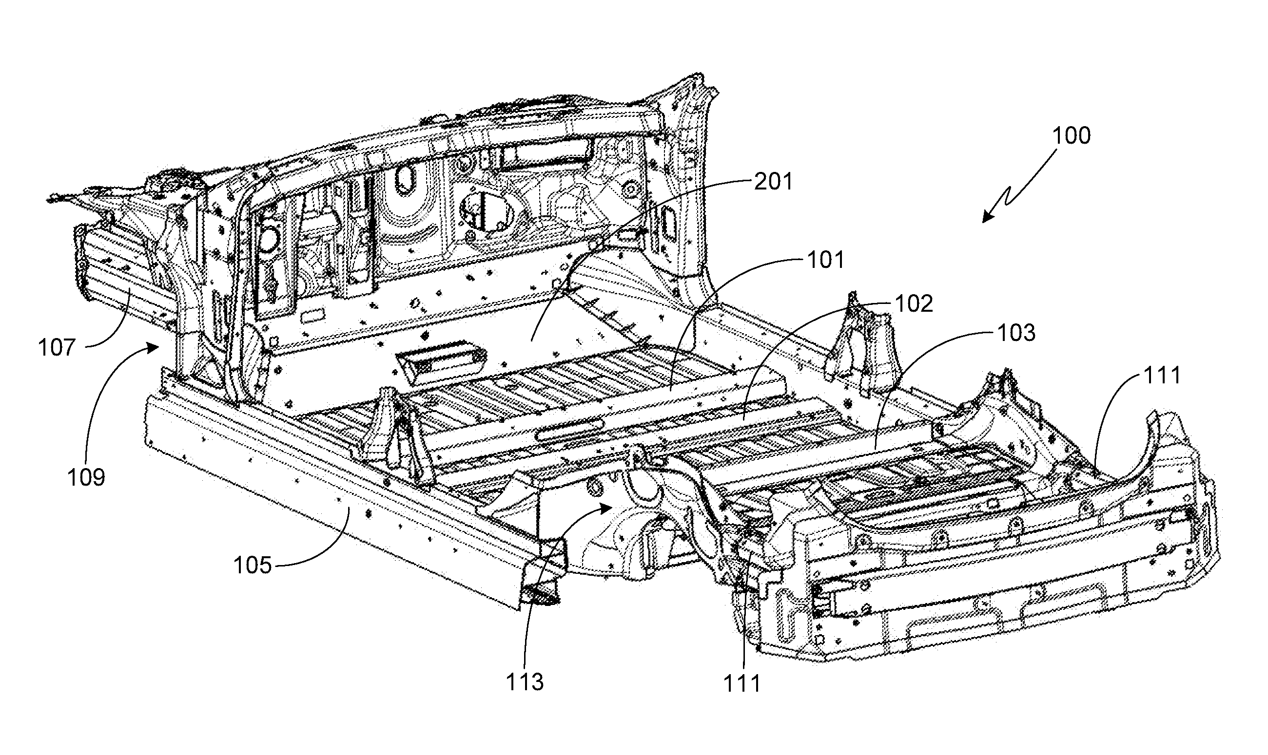
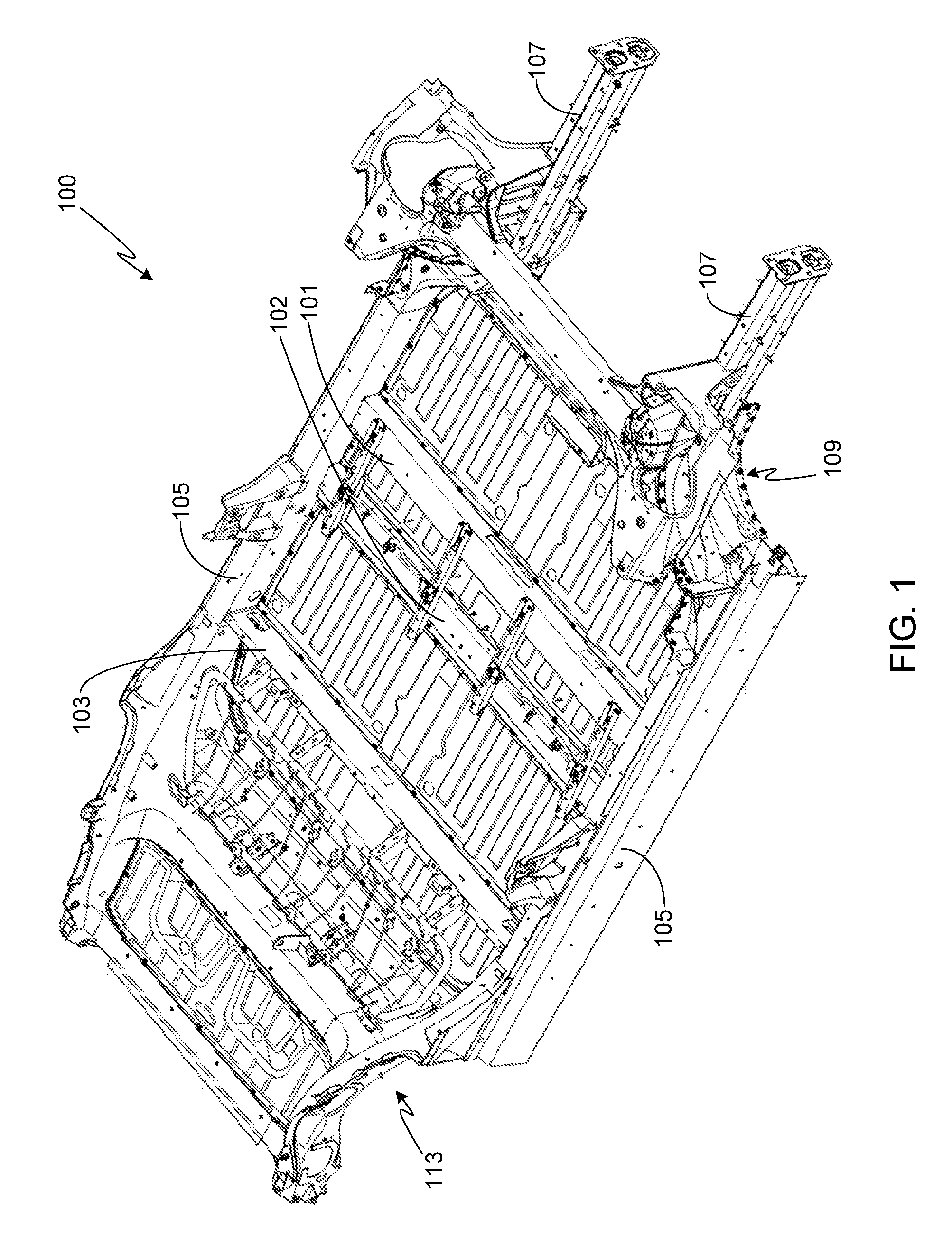
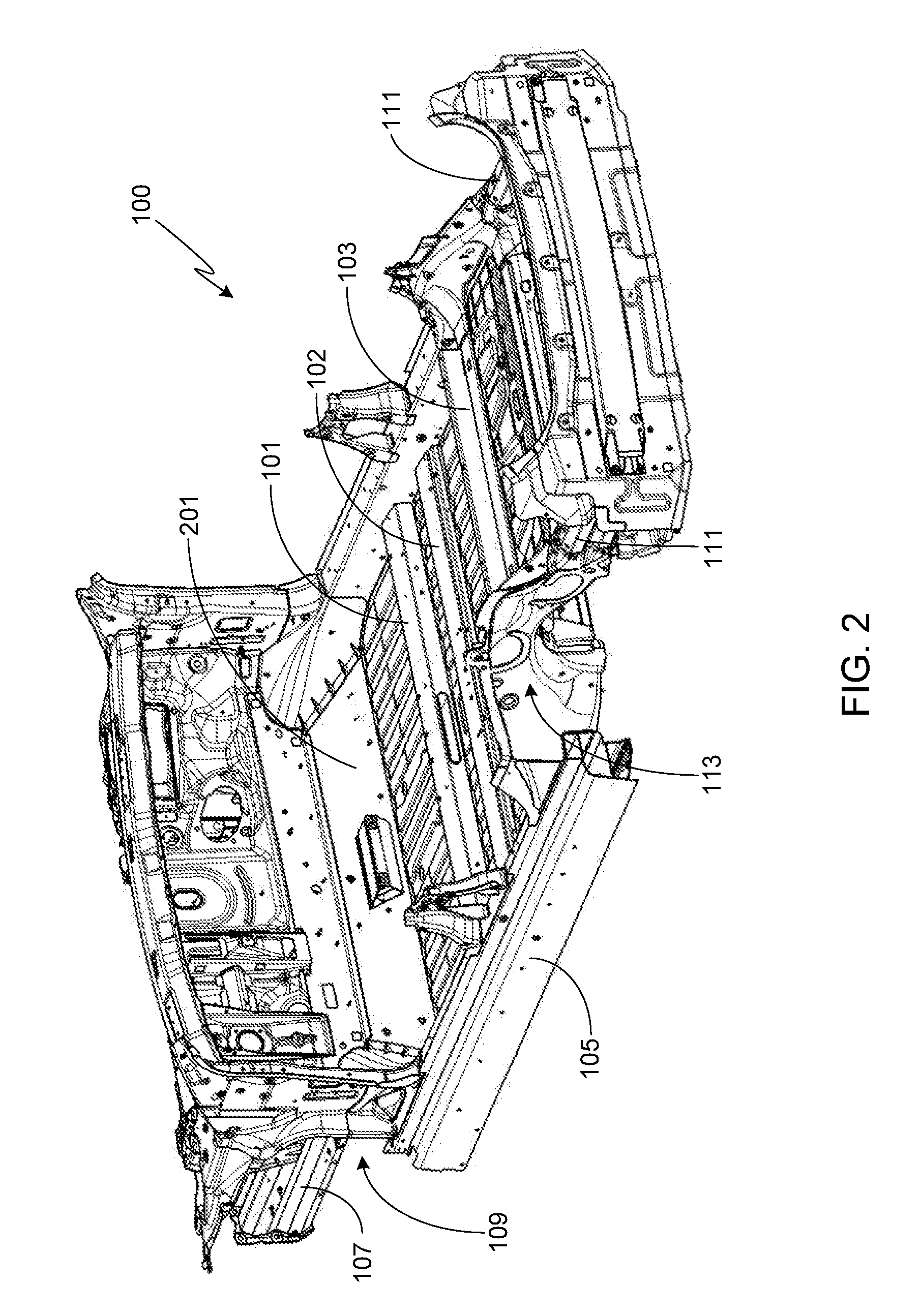
[0010]In another aspect, the impact energy absorbing component of each side sill assembly may include a reacting portion and a collapsible portion where the reacting portion is adjacent to the inner side sill wall and the collapsible portion is adjacent to the outer side sill wall. The impact energy absorbing component of each side sill assembly is preferably comprised of a sill insert that is captured between the inner and outer side sill walls, and preferably also captured between a substantially horizontal inner side sill wall and a pair of insert guide members where one of the insert guide members extends from an inner surface of the inner side sill wall and the other insert guide member extends from an inner surface of the outer side sill wall. The sill insert may be held in place using a plurality of fasteners (e.g., rivets, bolts, spot welds, adhesives, etc.). The sill insert may have a rectangularly-shaped cross-section and extend longitudinally within the side sill from a first side sill end portion proximate to one of the front torque boxes to a second side sill end portion proximate to one of the rear torque boxes. The sill insert may include a vertical internal wall that separates the reacting and collapsible portions of the insert. The reacting portion of the sill insert may be substantially square-shaped. The collapsible portion of the sill insert may be comprised of a pair of diagonal structural members that cross to form an x-shape, or two pairs of diagonal structural members each of which cross to form an x-shape, where the diagonal structural members extend between an upper sill insert wall and a lower sill insert wall. If the collapsible portion includes two pairs of diagonal structural members, the first pair of diagonal structural members closest to the outer side sill wall may be configured to collapse and deform prior to the second pair of diagonal structural members during a side impact collision.
[0011]In other aspects: the rear torque boxes may be welded to the side sill assemblies and the rear torque box cross-member(s) may be welded to the left / right rear torque boxes; the front torque boxes may be welded to the side sill assemblies; a toe board cross-member may be interposed and mechanically coupled to the left / right front torque boxes; the side sill assemblies may be fabricated from an aluminum extrusion, an aluminum alloy extrusion or a steel extrusion; the impact energy absorbing component may be fabricated from an aluminum alloy; each of the side members of the battery pack enclosure may include an extended region that is mechanically coupled (e.g., via bolts) to the corresponding side sill assemblies; the battery pack cross-members may include one or more cavities that extend along their length; and the battery pack cross-members may include an upper member mechanically coupled to the battery pack enclosure top panel and a lower member mechanically coupled to the battery pack enclosure bottom panel.

Problems solved by technology

Side impact collisions present a particularly challenging problem to vehicle safety engineers, both due to the relatively low position of the rocker panels on many small vehicles as well as the difficulty of implementing an impact resistant side structure while taking into account vehicle doors and doorways.
Although vehicle manufacturers use a variety of structures and components to protect a vehicle's occupants during a side impact collision, typically these approaches provide only limited protection while significantly increasing vehicle weight.

Method used


Image

  • System for Absorbing and Distributing Side Impact Energy Utilizing an Integrated Battery Pack and Side Sill Assembly
  • System for Absorbing and Distributing Side Impact Energy Utilizing an Integrated Battery Pack and Side Sill Assembly
  • System for Absorbing and Distributing Side Impact Energy Utilizing an Integrated Battery Pack and Side Sill Assembly

Examples


Embodiment Construction

[0034]In the following text, the terms “battery”, “cell”, and “battery cell” may be used interchangeably and may refer to any of a variety of different cell types, chemistries and configurations including, but not limited to, lithium ion (e.g., lithium iron phosphate, lithium cobalt oxide, other lithium metal oxides, etc.), lithium ion polymer, nickel metal hydride, nickel cadmium, nickel hydrogen, nickel zinc, silver zinc, or other battery type / configuration. The term “battery pack” as used herein refers to multiple individual batteries contained within a single piece or multi-piece housing, the individual batteries electrically interconnected to achieve the desired voltage and capacity for a particular application. The term “electric vehicle” as used herein may refer to an all-electric vehicle, also referred to as an EV, a plug-in hybrid vehicle, also referred to as a PHEV, or a non-plug-in hybrid vehicle, also referred to as a HEV, where a hybrid vehicle utilizes multiple propuls...


PUM


Abstract

An energy absorbing and distributing side impact system for use with a vehicle is provided, the system utilizing a collapsible side sill along with multiple vehicle cross-members to achieve the desired level of vehicle side impact resistance, the combination of these elements absorbing and distributing the impact load throughout the vehicle structure. A battery pack enclosure that includes a plurality of cross-members that transverse the battery pack enclosure also help to absorb and distribute at least a portion of the load received when either the first or second side of the vehicle receives a side impact. In this configuration the battery pack enclosure is positioned between the front and rear vehicle suspension assemblies and mounted between, and mechanically coupled to, the side sill assemblies. In addition to providing rigidity, strength and impact resistance, the battery pack cross-members segregate the batteries contained within the battery pack enclosure into battery groups.

Description

CROSS-REFERENCE TO RELATED APPLICATION[0001]The present application is a continuation-in-part of U.S. patent application Ser. No. 13 / 308,300, filed 30 Nov. 2011, which claims benefit of the filing date of U.S. Provisional Patent Application Ser. No. 61 / 426,254, filed 22 Dec. 2010, the disclosures of which are incorporated herein by reference for any and all purposes.FIELD OF THE INVENTION[0002]The present invention relates generally to vehicle structures and, more particularly, to means for enhancing the side impact performance of a vehicle.BACKGROUND OF THE INVENTION[0003]Modern vehicles use a variety of structures to protect the vehicle's occupants during a crash. Some of these structures are used to control the transmission of the crash energy to the passenger compartment while other structures, such as seat belts, head restraints, and air bags, are intended to restrain passenger movement during a crash, thereby preventing the passengers from hurting themselves as their bodies re...

Claims


Application Information

Patent Timeline
Patent Type & Authority Applications(United States)
IPC IPC(8): B62D21/15
CPCB62D21/157B60K1/04B62D25/2036B62D25/20B62D25/025B62D27/023
Inventor CHARBONNEAU, ALEXIBURGESS, MALCOLMATTALURI, VIVEKGADHIYA, HITENDRA LAXMIDASCLARKE, ALAN PAULRAWLINSON, PETER DORESUMPF, JR., ROBERT DAVIDEDWARDS, BRUCE PHILIP
Owner TESLA INC
Why Eureka
Try Eureka