
Transmit and receive phased array for automotive radar improvement

a phased array and radar technology, applied in the direction of instruments, instruments, measurement devices, etc., can solve the problems of increasing overall noise, reducing accuracy, and reducing the accuracy of the detection of false targets, so as to reduce coupling and reduce the complexity of the chip

Inactive Publication Date: 2013-04-11
TOYOTA MOTOR ENGINEERING & MANUFACTURING NORTH AMERICA
View PDF9 Cites 34 Cited by
  • Summary
  • Abstract
  • Description
  • Claims
  • Application Information

AI Technical Summary

Benefits of technology

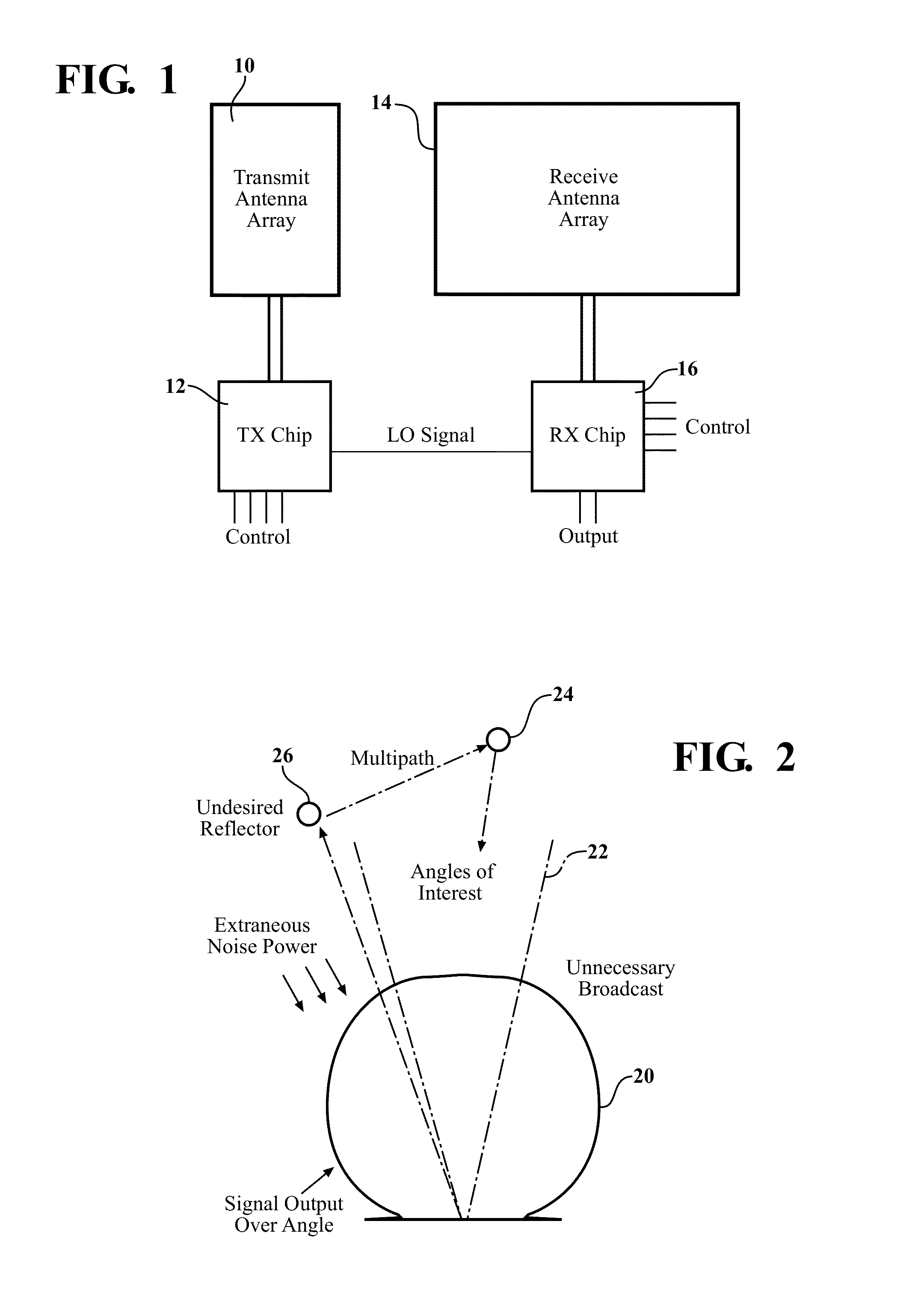
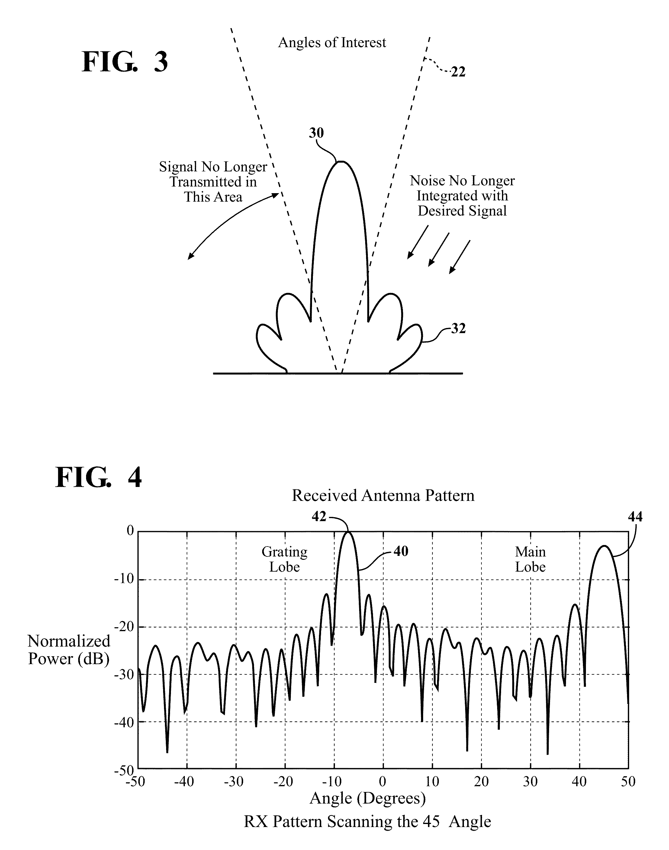
The invention is related to phased array radars used in automotive applications. The invention reduces coupling between the transmit and receive channels, which simplifies the design of the radar. The receive antenna elements are positioned close enough to avoid grating lobes, which increases the gain, but may cause grating lobes at angles to the straight bore sight. However, the effect of grating lobes is minimized by steering the transmit phased array so that a null in the transmit antenna pattern generally coincides with the corresponding incoming angle of the grating lobe generated by the receive antenna. Furthermore, increasing the receive antenna gain narrows the antenna beam, allowing higher signal-to-noise ratios.

Problems solved by technology

DBF uses antennas with wide beams, which causes the reception of unwanted signals.
The effect is to increase overall noise, and to create difficulties with false target detection.

Method used


Image

  • Transmit and receive phased array for automotive radar improvement
  • Transmit and receive phased array for automotive radar improvement
  • Transmit and receive phased array for automotive radar improvement

Examples


example radar

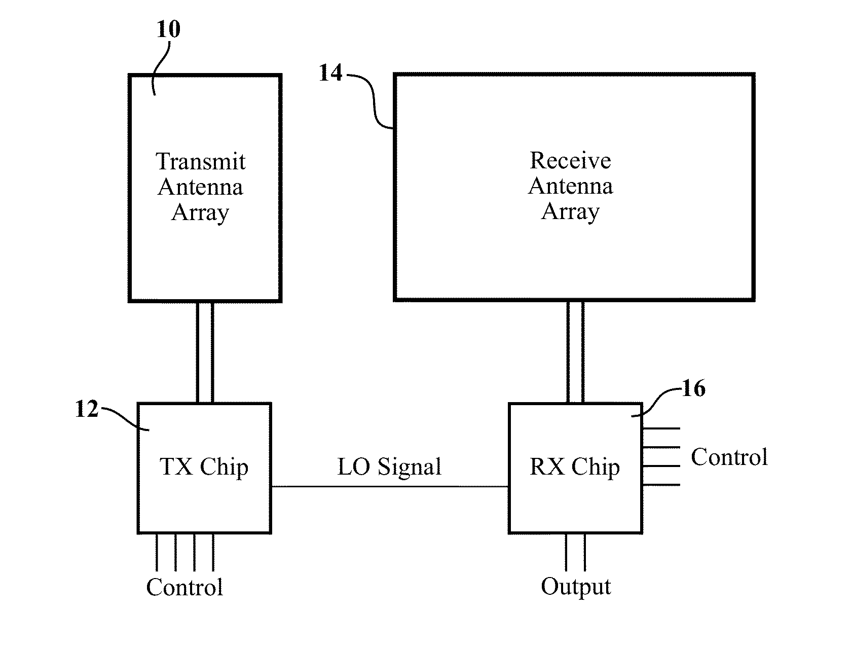
[0016 apparatus have a transmit-receive phased array architecture that requires only two control chips mounted onto an antenna board. The improved configuration provides a reduction in overall noise level, resulting in significant improvement of target discrimination. The problem of ghost targets is reduced, for example by reduction of multipath reflections. Further, the radar manufacturing process is relatively simple, and may be fabricated with low cost and complexity.

[0017]An example phased array radar apparatus includes a transmit antenna array, a receive antenna array, and an electronic control circuit, in electronic communication with the transmit and receive antenna arrays. The transmit beam, generated by the transmit array, and the receive beam, received by the receive array, are each steerable by the electronic control circuit so the main lobe of the transmit beam remains generally aligned with the main lobe of the receive beam, and the grating lobe of the receive beam rema...


PUM


Abstract

Examples of the present invention include methods and apparatus for phased array automotive radar which allow reductions in erroneous detections such as sidelobe clutter and ghost images. An example radar includes a steerable transmit antenna and a steerable receive antenna. Transmit and receive beams may be steered using an electronic control circuit so the main lobe of the transmit beam remains generally aligned with the main lobe of the receive beam, and the side lobe of the receive beam remains generally aligned with a null in the transmit beam.

Description

FIELD OF THE INVENTION[0001]The invention includes apparatus and methods for improved automotive radar, in particular phased array radar.BACKGROUND OF THE INVENTION[0002]Many current automotive radars use digital beam forming (DBF) to determine the bearing of a target. DBF uses antennas with wide beams, which causes the reception of unwanted signals. The effect is to increase overall noise, and to create difficulties with false target detection.[0003]Hence, it would be very valuable to develop improved automotive radars, which allow reduction in false target detection while being capable of low cost fabrication for automotive applications.SUMMARY OF THE INVENTION[0004]Examples of the present invention include phased array radars for use in automotive applications. An example apparatus includes a transmit antenna array, a receive antenna array, a transmit chip in electronic communication with the transmit antenna array, and a receiver chip in electronic communication with the receive...

Claims


Application Information

Patent Timeline
IPC IPC(8): H01Q3/00G01S13/931
CPCG01S7/354G01S2013/0245G01S13/931G01S13/34
Inventor LEE, JAE SEUNGSCHMALENBERG, PAUL DONALD
Owner TOYOTA MOTOR ENGINEERING & MANUFACTURING NORTH AMERICA
Learn More