Turbine engine blade made of composite material, and a method of fabricating it

Active Publication Date: 2013-04-11
SN DETUDE & DE CONSTR DE MOTEURS DAVIATION S N E C M A +1
View PDF6 Cites 41 Cited by
  • Summary
  • Abstract
  • Description
  • Claims
  • Application Information

AI Technical Summary

Benefits of technology

[0005]A main object of the present invention is thus to mitigate such drawbacks by proposing a blade of composite material that forms a single

Problems solved by technology

The blade obtained by such a method presents the drawback that its outer platform cannot incorporate both a function of providing sealing with the casing that surrounds the blades (by having wipers present) and an aerodynamic function (by having overhangs present that define the outside of the flow pa

Method used


Image

  • Turbine engine blade made of composite material, and a method of fabricating it
  • Turbine engine blade made of composite material, and a method of fabricating it
  • Turbine engine blade made of composite material, and a method of fabricating it

Examples


Embodiment Construction

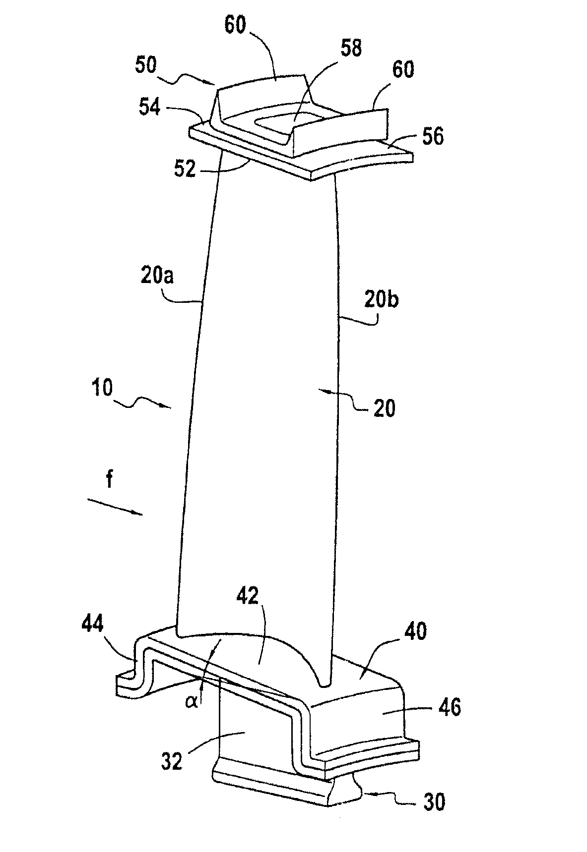
[0039]The invention is applicable to various types of turbine engine blade having inner and / or outer platforms incorporated therein, in particular compressor and turbine blades of various gas turbine spools, e.g. a low pressure (LP) turbine rotor blade such as that shown in FIG. 1.

[0040]The blade 10 of FIG. 1 comprises in well-known manner an airfoil 20, a root 30 constituted by a portion of greater thickness, e.g. having a bulb-shaped section and extended by a tang 32, an inner platform 40 situated between the tang 32 and the airfoil 20, and an outer platform 50 in the vicinity of the free end of the blade.

[0041]The airfoil 20 extends in a longitudinal direction between the inner platform 40 and the outer platform 50 and in cross-section it presents a curved profile of varying thickness between its leading edge 20a and its trailing edge 20b.

[0042]The blade 10 is mounted on a turbine rotor (not shown) by engaging the root 30 in a housing of complementary shape formed at the periphe...


PUM

PropertyMeasurementUnit
Timeaaaaaaaaaa
Weightaaaaaaaaaa
Thicknessaaaaaaaaaa

Abstract

A turbine engine blade made of composite material including fiber reinforcement densified by a matrix is fabricated by a method including: performing three-dimensional weaving to make a single-piece fiber blank; shaping the fiber blank to obtain a single-piece fiber preform having a first portion forming a preform for a blade root and an airfoil, at least one second portion forming a preform for a blade inner platform or for wipers of a blade outer platform, and at least one third portion forming a preform for reinforcing a blade inner platform or for overhangs of a blade outer platform; and densifying the fiber preform with a matrix to obtain a composite material blade having fiber reinforcement constituted by the preform and densified by the matrix, and forming a single piece with an inner and/or outer platform incorporated therein.

Description

BACKGROUND OF THE INVENTION[0001]The invention relates to turbine engine blades made of composite material comprising fiber reinforcement densified by a matrix.[0002]The intended field is that of gas turbine blades for aeroengines or industrial turbines.[0003]Proposals have already been made to fabricate composite material blades for turbine engines. Reference may be made in particular to patent applications FR 2 939 129 and FR 2 939 130 filed jointly by Snecma and Snecma Propulsion Solide. Those applications describe in particular fabricating a turbine engine blade out of composite material comprising fiber reinforcement densified by a matrix. More precisely, the method described in those two documents and applied to fabricating a blade presents the special feature of a fiber blank that is made by three-dimensional weaving and that is shaped in order to obtain a single-piece fiber preform with a first portion forming a preform for a blade root and an airfoil, and at least one secon...

Claims


Application Information

Patent Timeline
IPC IPC(8): F01D5/14B23P15/04
CPCC04B35/571Y10T29/49337C04B35/62873C04B35/62884C04B35/62897C04B35/806C04B2235/5244C04B2235/5252C04B2235/614C04B2235/616D03D11/02D03D25/005F01D5/282Y02T50/67Y02T50/672Y02T50/673B23P15/04F01D5/147F05D2300/6012F05D2300/603F05D2300/614C04B35/62868B29B11/16Y02T50/60C04B35/80
Inventor NUNEZ, ROMAINBLANCHARD, STEPHANERENON, GUILLAUMECOUPE, DOMINIQUEROUSSILLE, CLEMENT
Owner SN DETUDE & DE CONSTR DE MOTEURS DAVIATION S N E C M A
Why Eureka
Try Eureka