RF transmitter for electrically short antenna

a short antenna and rf technology, applied in the field of radiofrequency (rf) transmitters, can solve the problems of low efficiency, short antennas inherently exhibit low radiation resistance and low efficiency, and many apparatuses do not have enough room for an antenna large,

Active Publication Date: 2013-04-11
OTICON
View PDF5 Cites 7 Cited by
  • Summary
  • Abstract
  • Description
  • Claims
  • Application Information

AI Technical Summary

Problems solved by technology

However, many apparatuses do not have room for an antenna large enough to satisfy this condition.
Electrically short antennas inherently exhibit low radiation resistance and low efficiency.
The disclosed synthesizer radiating system comprises relatively complex circuits for controlling the switching devices.
Furthermore, the switching takes place at relatively high frequencies, which causes relatively high power losses in the electronic circuits that control the switching.
Therefore, the disclosed system is less suitable for low-power transmitters wherein such losses in the control circuits could easily exceed the actual transmit power.
Otherwise, the receiver must be able to adapt to changes of the signal frequency, phase and amplitude, which may put undesired limitations on e.g. the achievable communication range, the achievable data rate, the usable receiver circuit types, etc.
This forces the designer to make a trade-off b

Method used


Image

  • RF transmitter for electrically short antenna
  • RF transmitter for electrically short antenna
  • RF transmitter for electrically short antenna

Examples


Embodiment Construction

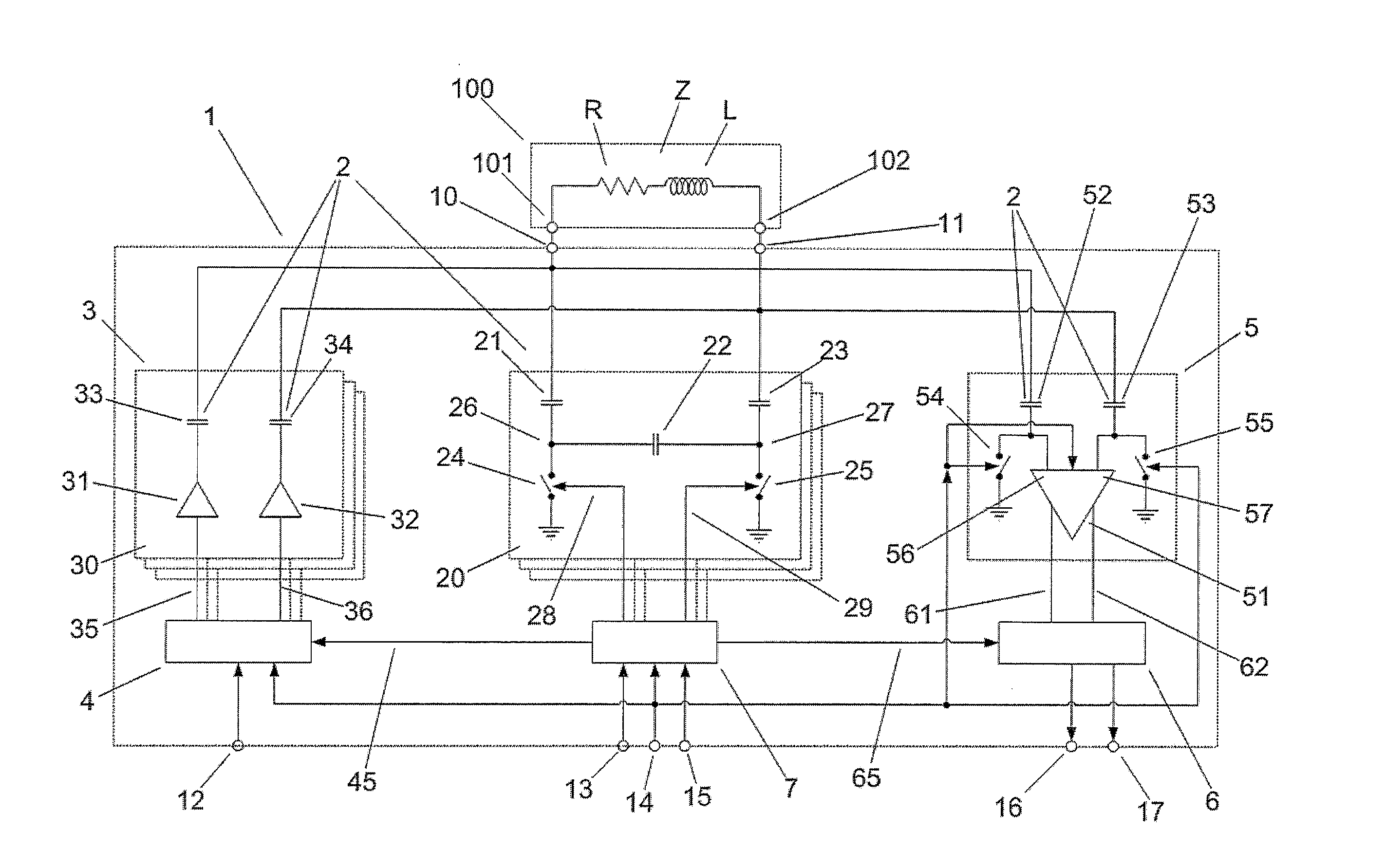
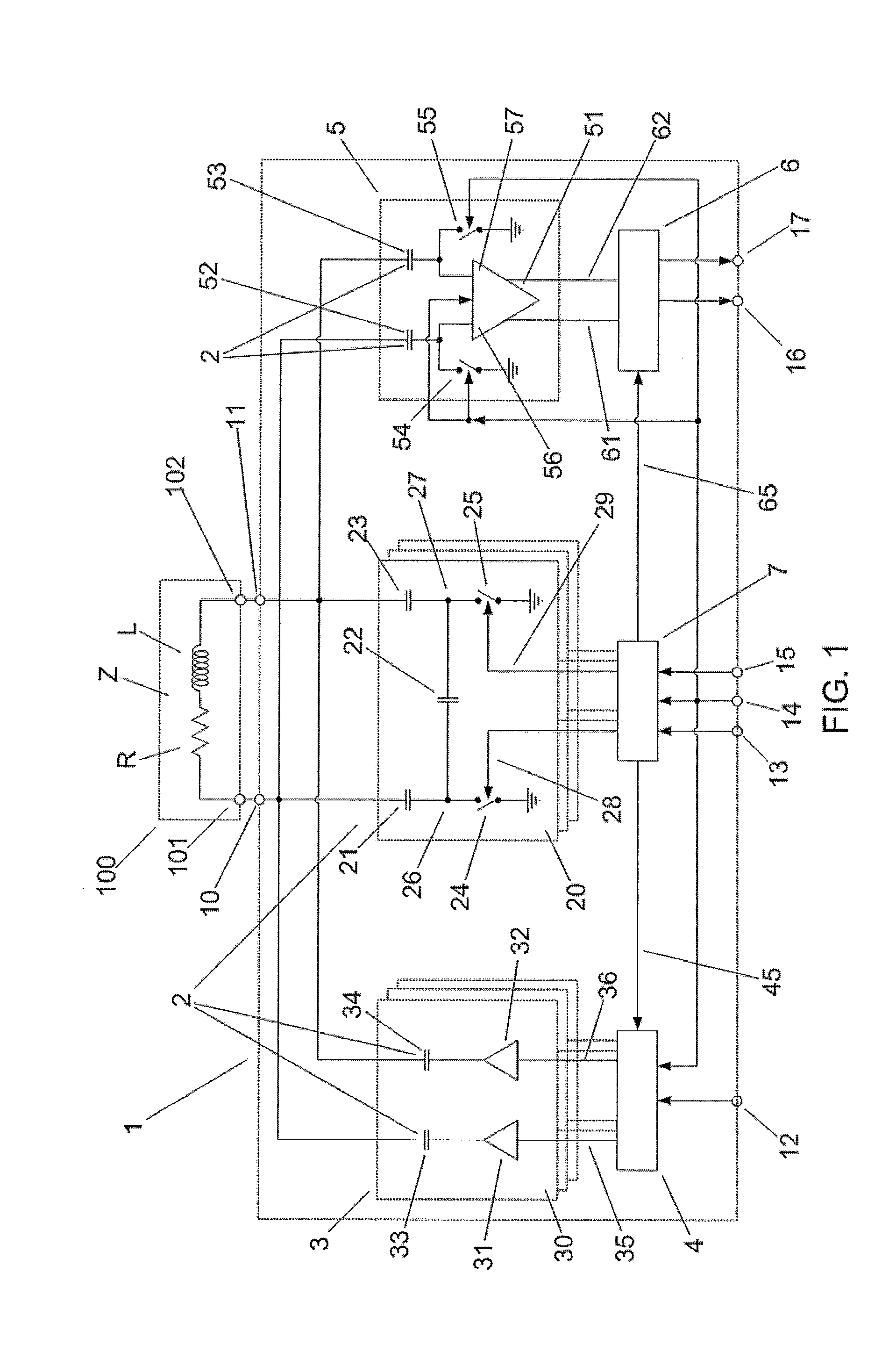
[0045]The transmitter 1 shown in FIG. 1 comprises a reactive energy storage 2, a power amplifier 3, a modulator 4, a receiver circuit 5, a demodulator 6, a control unit 7, two antenna output terminals 10, 11 for providing an electric transmission signal, a clock terminal 12 for receiving a clock signal, a data input terminal 13 for receiving an information signal D (see FIG. 3), a mode input terminal 14 for receiving a mode control signal, a tuning input terminal 15 for receiving a tuning control signal, a receive data terminal 16 for providing a receive data signal and a calibration data terminal 17 for providing a calibration data signal.

[0046]The energy storage 2 comprises 257 storage circuits 20, one of which is shown in the figure, as well as a number of capacitors 33, 34, 52, 53 that are also comprised in respectively the power amplifier 3 and the receiver circuit 5. Each storage circuit 20 comprises three tuning capacitors 21, 22, 23 and two tuning switches 24, 25. The tuning...


PUM


Abstract

A synthetic-frequency RF transmitter is provided for transmitting an electromagnetic signal via an electrically short antenna. The transmitter comprises a reactive energy storage with an effective reactance adapted to form with the antenna a resonance circuit with a resonance frequency and a driver adapted to provide to the resonance circuit an electric transmission signal having an instantaneous frequency that varies in dependence on an information signal. The transmitter is characterised in that the transmitter is adapted to dynamically change the resonance frequency by changing the effective reactance in dependence on the information signal. Thus, the instantaneous pass-band of the resonance circuit may be controlled to substantially always comprise the instantaneous frequency of the electric transmission signal and thus of the electromagnetic signal.

Description

TECHNICAL FIELD[0001]The present invention relates to a radio-frequency (RF) transmitter for transmitting electromagnetic signals via an electrically short antenna.[0002]The invention may e.g. be useful in wireless communication involving portable and / or battery-operated apparatuses, such as wireless communication between hearing devices and auxiliary devices. Hearing devices may e.g. be hearing aids for compensating for a hearing-impaired person's loss of hearing capability or listening devices for augmenting a normal-hearing person's hearing capability.BACKGROUND ART[0003]RF antennas for transmission of electromagnetic signals are preferably designed to have a size of at least one quarter of the wavelength of the transmitted signal, since this generally allows high antenna efficiency, wide bandwidth and substantially real input impedance. However, many apparatuses do not have room for an antenna large enough to satisfy this condition. For an RF signal with a frequency of e.g. 100 ...

Claims


Application Information

Patent Timeline
IPC IPC(8): H04B1/04
CPCH03J2200/06H03J1/0008
Inventor CHRISTENSEN, KARE TAIS
Owner OTICON
Why Eureka
Try Eureka