System and method for automatically controlling energy apparatus using energy modeling technique

a technology of energy modeling and energy apparatus, applied in adaptive control, computer control, instruments, etc., can solve the problems of inability to systemically control energy consumption for users, difficult balance between supply and demand of energy, and limitation in improving energy efficiency, so as to improve energy efficiency, manage energy more efficiently, and minimize energy was

Inactive Publication Date: 2013-04-11
EZVILLE +1
View PDF12 Cites 20 Cited by
  • Summary
  • Abstract
  • Description
  • Claims
  • Application Information

AI Technical Summary

Benefits of technology

[0020]The exemplary embodiments of the present invention may automatically control an energy apparatus using an energy modeling technique to minimize wasting of energy and improve energy efficiency.
[0021]The exemplary embodiments of the present invention may manage energy more efficiently by adaptively controlling energy depending on a change in the surrounding environment such as an absence of residents, weather, seasonal variations, and temperature / humidity.
[0022]The exemplary embodiments of the present invention may collect and organize usage information of an energy apparatus used in an apartment, a house or a building and environment information, and may determine an optimum energy efficiency through energy modeling. Accordingly, the exemplary embodiments of the present invention may efficiently manage energy consumption by automatically controlling the energy apparatus using a determined value to obtain the optimum energy efficiency.

Problems solved by technology

Recently with the rise of climate change and energy problems as global concerns, issues such as power consumption and carbon emission are being raised as key issues in many fields.
As a result, the balance between supply and demand of energy is difficult, and in particular, systematic energy consumption is impossible for users.
However, because this conventional energy management system controls an energy apparatus based only on a value set by a user, there is a limitation in improving the energy efficiency.

Method used


Image

  • System and method for automatically controlling energy apparatus using energy modeling technique
  • System and method for automatically controlling energy apparatus using energy modeling technique
  • System and method for automatically controlling energy apparatus using energy modeling technique

Examples


Embodiment Construction

[0027]Reference will now be made in detail to exemplary embodiments of the present invention, examples of which are illustrated in the accompanying drawings, wherein like reference numerals refer to the like elements throughout. Exemplary embodiments are described below to explain the present invention by referring to the figures.

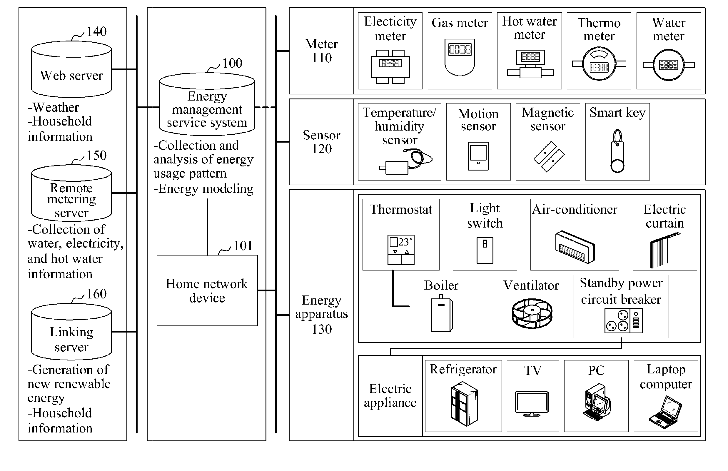
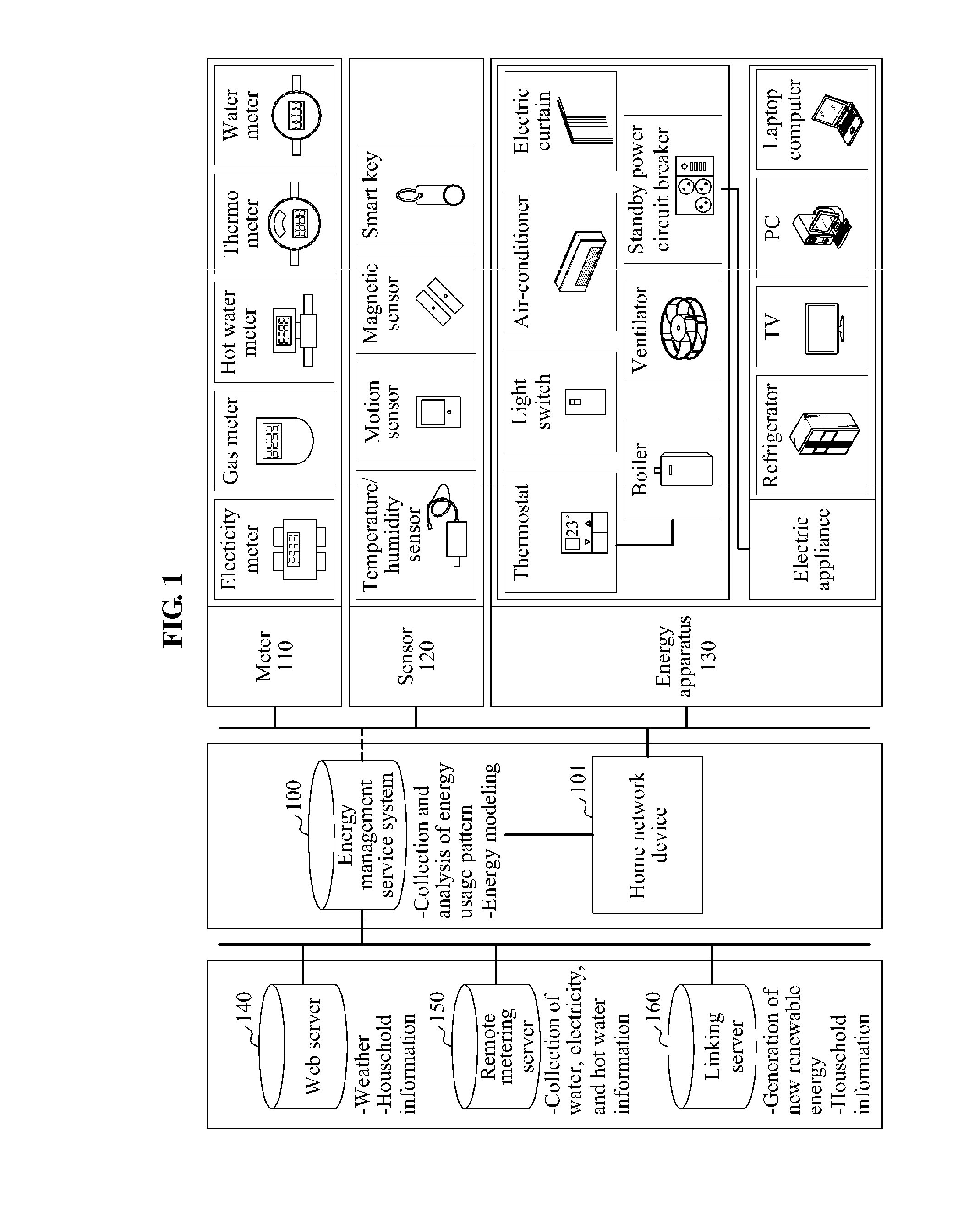
[0028]Exemplary embodiments of the present invention may be applied to an integrated energy management system that may monitor and control an amount of electricity, gas, or water consumed in each house or city facility, based on a power line communication (PLC) communication technique, in which a power line installed to supply electricity to each house or city facility is used as a communication line, and based on a wireless communication means such as internet protocol-ubiquitous sensor network (IP-USN), Wi-Fi, RF, and the like.

[0029]FIG. 1 is a diagram illustrating an entire configuration of an energy management service system using an energy modeling tec...


PUM


Abstract

A system and method for automatically controlling an energy apparatus using an energy modeling technique is disclosed. The energy management service system for managing the use of energy of each region may include an energy collecting unit to collect energy usage information of an energy apparatus consuming energy in a region through a remote metering server, an apparatus collecting unit to collect control state information of the energy apparatus through a home network device installed in the region to control the operation of the energy apparatus, and an energy management unit to determine an energy usage control factor based on the energy usage trend and to automatically control the operation of the energy apparatus based on the energy usage control factor.

Description

CROSS-REFERENCE TO RELATED APPLICATION[0001]This application claims the priority benefit of Korean Patent Application No. 10-2011-0102398, filed on Oct. 7, 2011, in the Korean Intellectual Property Office, the disclosure of which is incorporated herein by reference.BACKGROUND[0002]1. Field of the Invention[0003]Exemplary embodiments of the present invention relate to a system and method for automatically controlling an energy apparatus, using an energy modeling technique to minimize wasting of energy and improve energy efficiency.[0004]2. Description of the Related Art[0005]Recently with the rise of climate change and energy problems as global concerns, issues such as power consumption and carbon emission are being raised as key issues in many fields.[0006]Conventional energy consumption patterns are such that energy consumption and billing are made based on an initial contact between users and suppliers without a special control or management function. As a result, the balance betw...

Claims


Application Information

Patent Timeline
Patent Type & Authority Applications(United States)
IPC IPC(8): G06F1/28G05D23/19
CPCG05B17/02
Inventor LEE, CHU YONGPARK, HEUNG SOO
Owner EZVILLE
Why Eureka
Try Eureka