
Flexible circuit board

a flexible circuit board and circuit technology, applied in the direction of printed circuit aspects, box-like pcb arrangements, circuit thermal arrangements, etc., can solve the problem of short life span of the circuit element, and achieve the effect of maintaining the flatness of the heat dissipation layer and easy bending processing

Active Publication Date: 2013-04-18
NIPPON MEKTRON LTD
View PDF10 Cites 50 Cited by
  • Summary
  • Abstract
  • Description
  • Claims
  • Application Information

AI Technical Summary

Benefits of technology

The present invention provides a flexible circuit board with a heat dissipation layer that can bend easily and maintain flatness, while slimming down the circuit board.

Problems solved by technology

However, in cases where a large current is caused to flow through the flexible circuit board, an electric resistance connected to a wiring layer increases, or an amount of heat generated from a circuit element such as a light emitting device increases, as a result of which there arises a problem in which the circuit element may be damaged by thermal runaway, or the life span of the circuit element becomes short.

Method used


Image

  • Flexible circuit board
  • Flexible circuit board
  • Flexible circuit board

Examples


first embodiment

[0041][1-1: With Reference to Schematic Construction of Flexible Circuit Board]

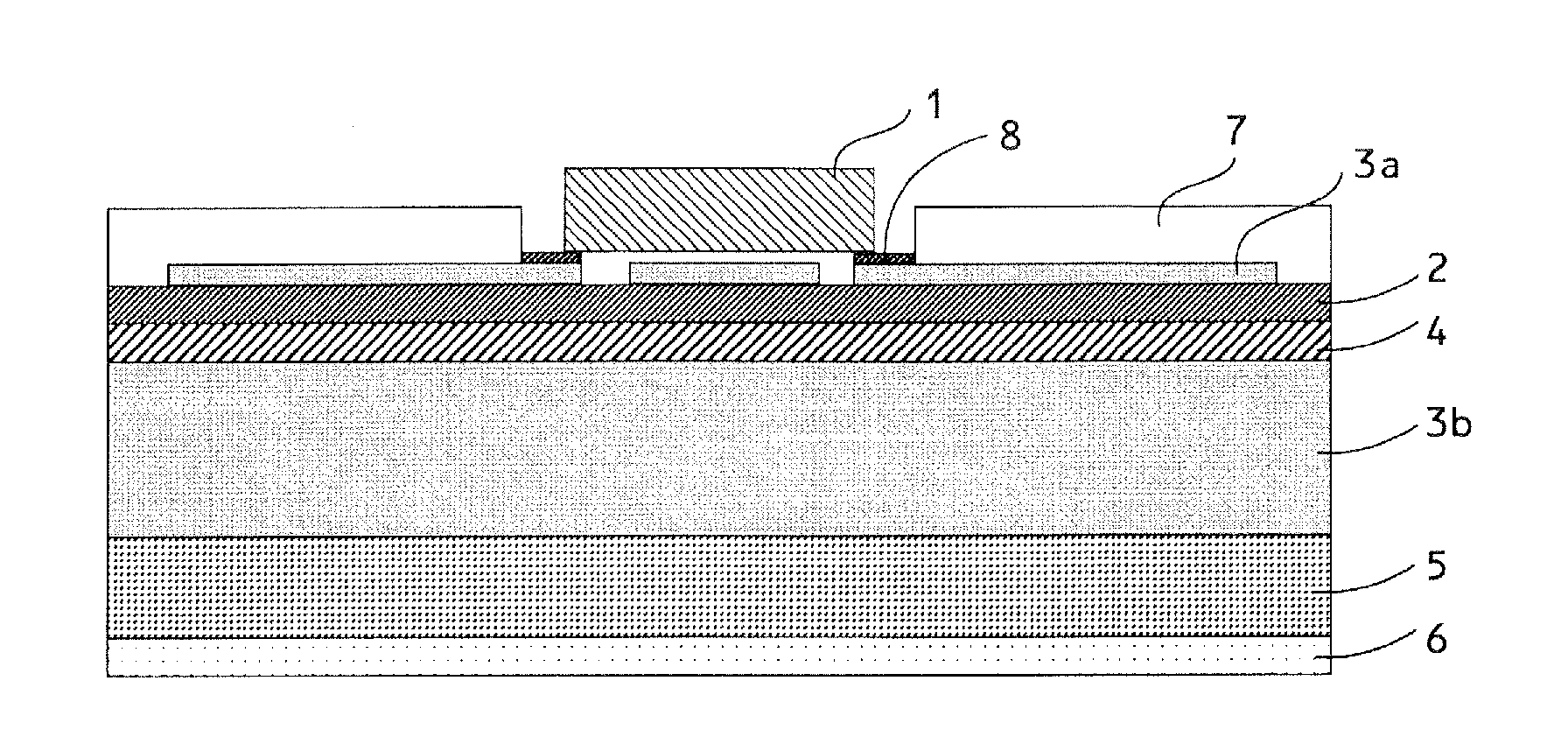
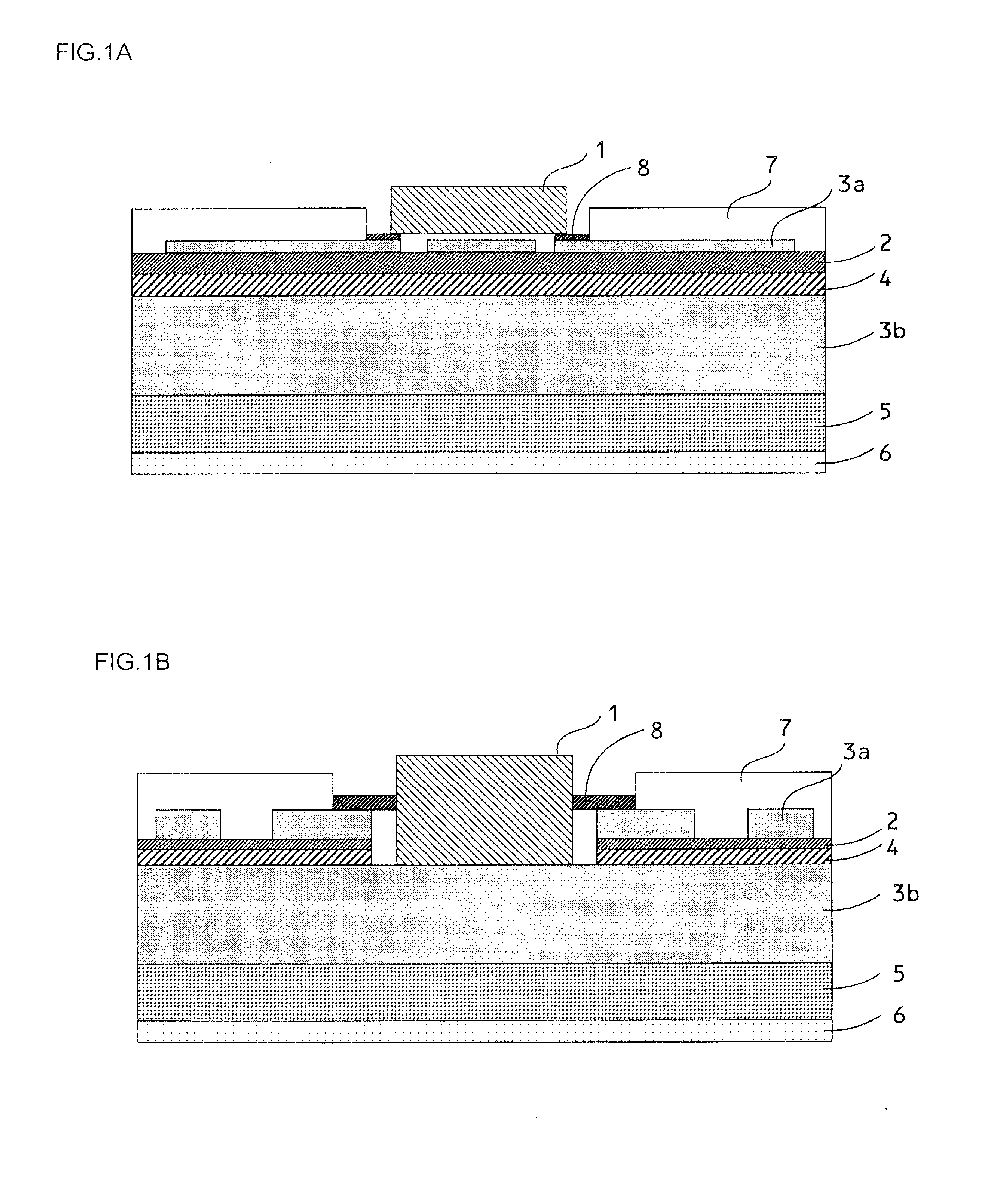
[0042]Reference will be made to the schematic construction of a flexible circuit board according to this first embodiment of the present invention, while referring to FIG. 1(a) and FIG. 1(b). FIG. 1(a) and FIG. 1(b) show the schematic constructions of the flexible circuit board according to the present embodiment, respectively.

[0043]The flexible circuit board is provided, at an upper side of a heat dissipation layer 3b (with a thickness of 100 μm-150 μm), with a thermally conductive adhesive layer 4, a polyimide film 2 (an insulating layer: about 3 μm in thickness), and a wiring layer 3a (18 μm or 35 μm in thickness), which are laminated one over another in this order, and is further provided, at a lower side of the heat dissipation layer 3b, with a high thermally conductive adhesive layer 5 (about 50 μm in thickness) attached with a protector paper 6. In addition, an upper side of the wiring layer 3a is ...

second embodiment

[0118]Reference will be made to a second embodiment to which the present invention can be applied, while referring to FIG. 6 and FIG. 7. The layer structure of a flexible circuit board according to this second embodiment is the same as that of the first embodiment, so the description thereof is omitted, and here, only differences of this second embodiment from the first embodiment will be explained.

[0119][2-1: With Reference to Heat Sink]

[0120]FIG. 6(a) shows one form of the flexible circuit board according to the first embodiment. Because bending processing can be carried out on the flexible circuit board according to the first embodiment in an easy manner, as stated above, the flexible circuit board can be processed into a stepped or staircase shape as illustrated in this figure, for example. The flexible circuit board of such a shape can be applied to a front lamp of an automobile, etc., for example.

[0121]FIG. 6(b) shows the schematic structure of the flexible circuit board accor...


PUM


Abstract

The present invention provides a flexible circuit board with a heat dissipation layer on which bending processing can be carried out easily, while achieving its slimming down, and which can maintain the flatness of the heat dissipation layer. The flexible circuit board, at least, has a wiring layer 3a adapted to be electrically connected to a circuit element, an insulating layer 2, and a heat dissipation layer 3b, and which is characterized in that said wiring layer 3a is formed of a copper foil which has a tensile strength of 250 MPa or less and a thickness of 50 μm or less, and said heat dissipation layer is formed of a copper foil which has a tensile strength of 400 MPa or more and a thickness of 70 μm or more.

Description

TECHNICAL FIELD[0001]The present invention relates to a flexible circuit board, and in particular, to a flexible circuit board which is excellent in heat dissipation.BACKGROUND ART[0002]In the past, flexible circuit boards have been known as circuit boards on which circuit elements are mounted. A flexible circuit board is one in which a wiring layer of a copper foil, etc., is formed on a surface of an insulating film as a substrate, and has characteristics that it is light in weight, thin in thickness, and is able to be bent in a flexible manner. As a result, in recent years, flexible circuit boards are used not only for electronic equipment but also for lighting equipment, etc., which uses an LED (Light Emitting Diode) as a light source, for example.[0003]On the other hand, in recent years, a demand to the operation of electronic equipment, the high speed and advancement of control, or an increase in the light emitting luminance of lighting equipment is increasing more and more, an...

Claims


Application Information

Patent Timeline
Patent Type & Authority Applications(United States)
IPC IPC(8): H05K1/02
CPCH05K1/0206H05K1/0298H05K1/0393H05K1/0201H05K2201/056H05K2201/10106H05K2201/047
Inventor KAJIYA, ATSUSHI
Owner NIPPON MEKTRON LTD
Learn More