Capacitive sensing system able of using heating element as antenna electrode

a capacitive measurement and antenna electrode technology, applied in the direction of instruments, pedestrian/occupant safety arrangements, vehicular safety arrangements, etc., can solve the problems of large cores of inductor wound on the inductor, the device may not operate in sensing mode and in heating mode, and the capacitive measurement circuit and the seat heater are high ac impedance at the same time. , to achieve the effect of high impedance and easy connection

Active Publication Date: 2013-04-18
IEE INT ELECTRONICS & ENG SA
View PDF1 Cites 36 Cited by
  • Summary
  • Abstract
  • Description
  • Claims
  • Application Information

AI Technical Summary

Benefits of technology

[0015]The present invention uses a common mode choke with a coupling factor close to unity to achieve AC-decoupling of the heating element from its power supply. The common mode choke produces high impedance against common mode currents from the heating element into the first and second windings. The capacitive sensing system according to the invention furthermore takes into account the fact that an actual common mode choke cannot perfectly block alternating current. The total residual alternating current across the common mode choke (i.e. the part that cannot be blocked) stands in a known relationship to the portion of the alternating current that flows across the third winding. By measuring this portion of the alternating current, the capacitive sensing system thus can determine the alternating current actually flowing across the capacitance of the heating element.
[0016]The capacitive sensing system as described above may be configured as a module so as to be easily connectable between to an existing heating element and its heating current supply. A preferred alternative aspect of the invention concerns a combined (integrated) heating and capacitive sensing system. Such a combined system comprises a heating element for producing heat when elect

Problems solved by technology

The device may not operate in sensing mode and in heating mode at a time.
A disadvantage of the system disclosed in U.S. Pat. No. 6,703,845 is that the inductors used as AC-decoupling elements have to support the full heating current (up to 10 A DC and more) and present high AC impedance to the capacitive measureme

Method used


Image

  • Capacitive sensing system able of using heating element as antenna electrode
  • Capacitive sensing system able of using heating element as antenna electrode
  • Capacitive sensing system able of using heating element as antenna electrode

Examples


Embodiment Construction

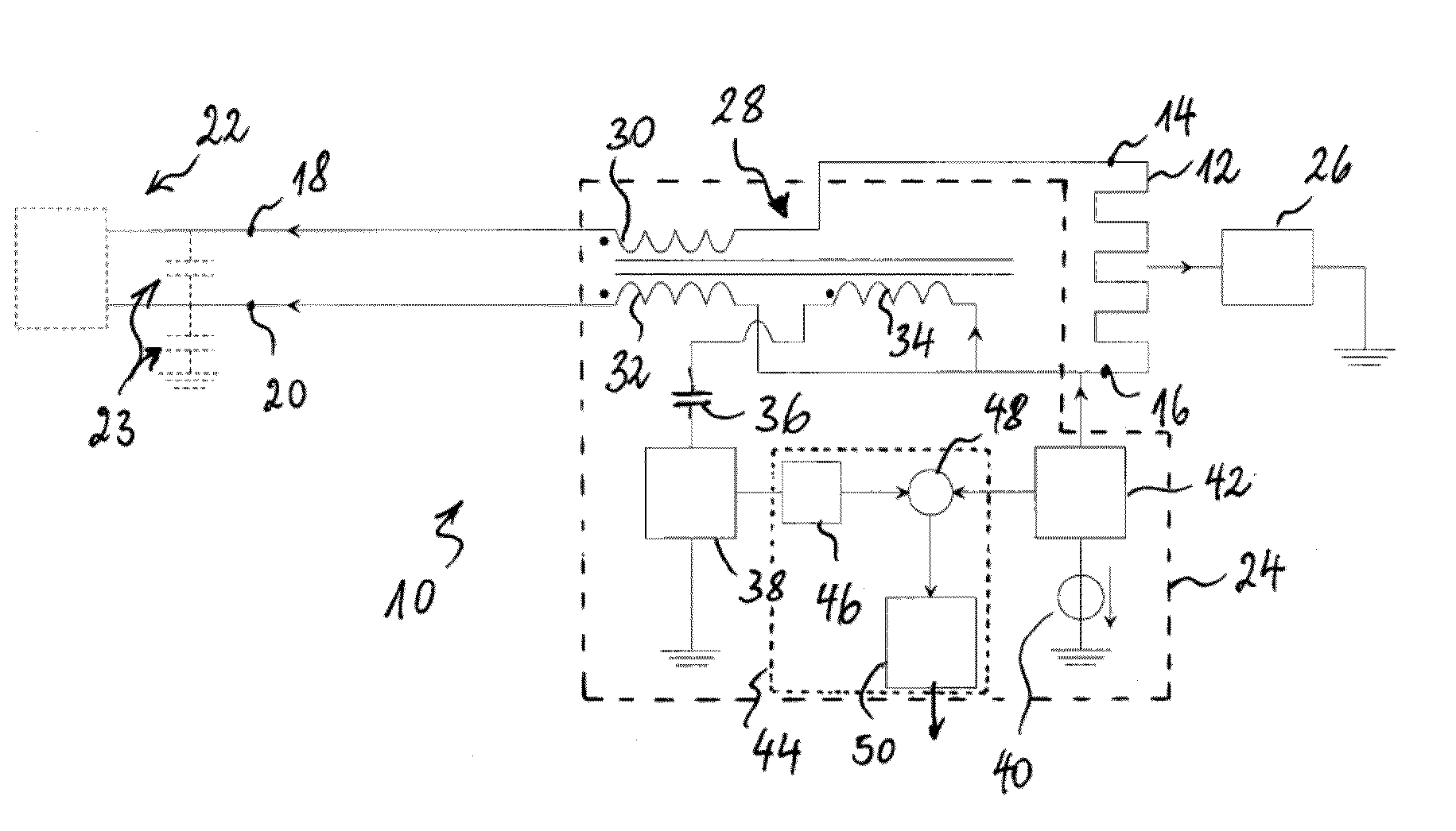
[0031]FIG. 1 shows a combined heating and capacitive sensing system 10 according to a first example of the invention. The combined system 10 comprises a heating element 12 that produces heat when electrical current is caused to flow across it. The heating element 12 may comprise a conductive wire, cable, fibre, bundle of fibres or a conductive track (e.g. made of a PTC material) printed on a flexible support. The heating element 12 has a first 14 and a second 16 terminal connected to a first 18 and a second 20 terminal of a heating current supply 22, respectively. The heating current supply 22 (e.g. a direct current source and control electronics) and the heating element 12 form together the heating circuit of a heater, e.g. for a vehicle seat. The terminals of the heating current supply 22 typically have low AC impedance to AC-ground (e.g. due to coupling capacitors 23) in order to avoid that AC signals disturb the heating current supply 22. The heating current supply preferably co...


PUM


Abstract

A capacitive sensing system for being connected to a heating element comprises a capacitive detector connectable to the heating element and a common mode choke for essentially preventing alternating current from flowing from the heating element to the heating current supply. The capacitive detector is configured for driving an alternating current into the heating element and for producing an output indicative of capacitance based upon the alternating current. The choke has a first and a second winding for connecting the heating element with the heating current supply. The choke comprises a third winding connected in parallel of the first and/or second winding. The capacitive detector is configured for measuring a portion of the alternating current flowing across the third winding and for taking into account the measured portion of alternating current when producing the output.

Description

TECHNICAL FIELD [0001]The present invention generally relates to a capacitive sensing system that can use a heating element as its antenna electrode. A capacitive sensing system as proposed herein may e.g. be used for detecting the absence or presence of an occupant on an occupiable item, which might be a vehicle seat, a hospital bed etc., or for detecting a driver's hand on the steering wheel.BACKGROUND ART[0002]A capacitive sensor, called by some electric field sensor or proximity sensor, designates a sensor, which generates a signal responsive to the influence of what is being sensed (a person, a part of a person's body, a pet, an object, etc.) upon an electric field. A capacitive sensor generally comprises at least one antenna electrode, to which is applied an oscillating electric signal and which thereupon emits an electric field into a region of space proximate to the antenna electrode, while the sensor is operating. The sensor comprises at least one sensing electrode at which...

Claims


Application Information

Patent Timeline
IPC IPC(8): H05B1/00G01R27/26
CPCB60N2/5685B62D1/046B60R21/0154B60N2/002B60R21/01532B62D1/065B60R21/015
Inventor VIRNICH, MICHAELHOYER, DAVIDTHINNES, MARTINPUETZ, MICHAELMEYERS, THOMASLAMESCH, LAURENT
Owner IEE INT ELECTRONICS & ENG SA
Why Eureka
Try Eureka