Pwm output apparatus and motor driving apparatus

a technology of output apparatus and motor, which is applied in the direction of motor/generator/converter stopper, pulse technique, dynamo-electric converter control, etc., can solve the problem of inability to precisely control the motor, and achieve the effect of accurate and smooth control, smooth increase of pulse width of second signal, and precise and smooth control

Active Publication Date: 2013-04-18
RENESAS ELECTRONICS CORP
View PDF17 Cites 11 Cited by
  • Summary
  • Abstract
  • Description
  • Claims
  • Application Information

AI Technical Summary

Benefits of technology

[0026]In the related technique, when the pulse width of the negative phase signal is small, the pulse width of the negative phase signal after the dead time insertion changes over a period between the width of 0 and the dead time period. On the other hand, in the present invention, when the pulse width is small, any dead time is not inserted in a second signal (e.g. negative phase signal) in the dead time period after the first signal (e.g. positive phase signal) is set to the active condition. When the pulse width exceeds a predetermined value, the pulse width of the second signal starts to increase smoothly. As a result, the precise and smooth control can be carried out even when the pulse width is small.
[0027]According to the PWM output apparatus of the present invention, the PWM output width can be correctly controlled in a small unit.

Problems solved by technology

As a result, there is a problem that the PWM output signal can not adjusted from the active or inactive condition sequentially in units of clock cycles so that the motor can not be precisely controlled.

Method used


Image

  • Pwm output apparatus and motor driving apparatus
  • Pwm output apparatus and motor driving apparatus
  • Pwm output apparatus and motor driving apparatus

Examples


Embodiment Construction

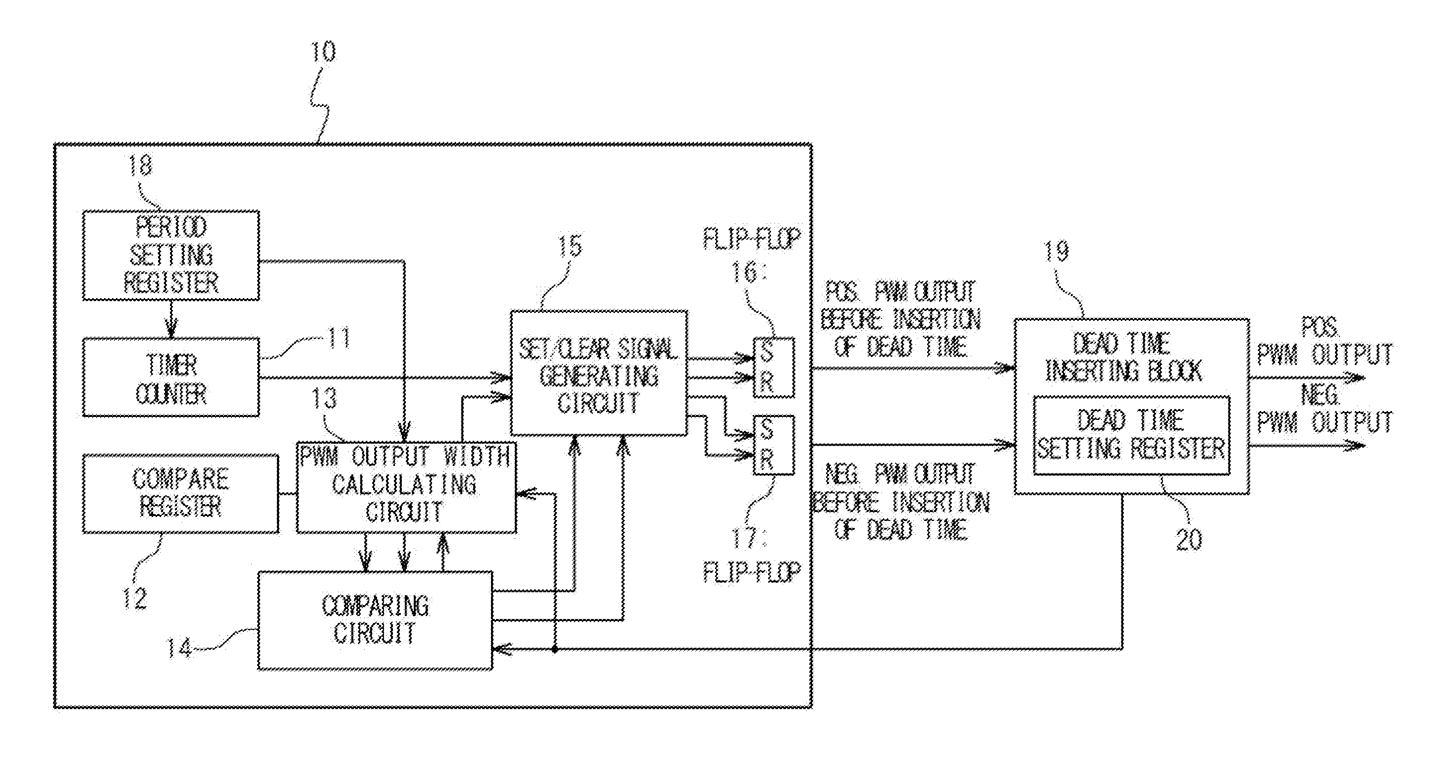
[0045]Hereinafter, embodiments of the present invention will be described with reference to the attached drawings. The PWM output apparatus for motor control according to a first embodiment of the present invention is provided with a dead time inserting block, a calculating circuit, a comparing circuit and a PWM signal generating circuit. The dead time inserting block sets a dead time period to the positive phase signal and the negative phase signal of the PWM output signal in order to prevent that the positive phase signal and the negative phase signal of the PWM output signal from being turned on simultaneously. The calculating circuit calculates a PWM output width before dead time insertion. The comparing circuit compares the calculated PWM output width and a predetermined dead time period. The PWM generating circuit outputs the PWM output signal before the dead time insertion to the dead time inserting block based on the comparison result of the comparing circuit.

[0046]When it i...


PUM


Abstract

A PWM output apparatus includes a calculating circuit configured to calculate an output width of a PWM output signal of a first signal and a second signal, which have phases different from each other, based on a command value of a PWM output. A comparing circuit compares the output width and a reference period which is set longer than a predetermined dead time period. A PWM output signal generating circuit outputs the PWM output signal to a dead time inserting block as a corrected PWM output signal, when a set / clear signal generating circuit outputs the set signal, and carries out a correction of setting the first signal of the PWM output signal to be inactive to output to the dead time inserting block as the corrected PWM output signal, when the set / clear circuit outputs the clear signal. The dead time inserting block corrects the corrected PWM output signal.

Description

CROSS REFERENCE[0001]This application claims a priority on convention based on Japanese Patent Application No. JP 2011-220655. The disclosure thereof is incorporated herein by reference.TECHNICAL FIELD[0002]The present invention is related to a semiconductor integrated circuit, and especially, to a PWM (Pulse Width Modulation) output apparatus for motor control, and a motor driving apparatus using the same.BACKGROUND ART[0003]In recent years, measures to environmental issues are requested worldwide. Especially, an energy saving request has become severe to home electronics products such as a washing machine and an air conditioner. A microcomputer installed with a PWM output apparatus is widely used to control a 3-phase motor installed in each of the home electronics products.[0004]Generally, the outputs of the 3 phases of U phase, V phase, and W phase are used to control the 3-phase motor. The PWM output apparatus outputs PWM control signals of a positive phase and a negative phase ...

Claims


Application Information

Patent Timeline
Patent Type & Authority Applications(United States)
IPC IPC(8): H02P27/08H03K7/08H02M7/48H03K5/05
CPCH02P27/08H02P23/00H03K7/08
Inventor MINAMI, MASAHIRO
Owner RENESAS ELECTRONICS CORP
Why Eureka
Try Eureka