
Aircraft wing cover comprising a sandwich panel and methods to manufacture and design the said wing cover

Active Publication Date: 2013-04-25
AIRBUS OPERATIONS LTD
View PDF8 Cites 21 Cited by
  • Summary
  • Abstract
  • Description
  • Claims
  • Application Information

AI Technical Summary

Benefits of technology

The invention is about a new way to make panels for aircraft that are stronger and lighter. The panels have a layer of foam to absorb the complicated structure of the panel. The way the foam is arranged helps to make the panels more efficient and reduces the need for additional reinforcement. This makes the panels stronger and lighter, and makes them easier to assemble and modify.

Problems solved by technology

With the use of composite materials becoming more prevalent within the aircraft industry, it has become apparent that issues relating to the control of interfaces between components of large, complex, composite structures have become more of a challenge.
In the case of an aircraft wing, the interfaces between wing spars, ribs and covers (skins) for a commercial airliner, for example, are particularly difficult to control.
This is primarily due to the difficulty in controlling the through thickness tolerance associated with complex laminate composite components, especially when there are ramps (thickness variations) within these components.
This problem is a function of both the through thickness tolerance of individual plies within the laminate, as well as the location of the ply edges, which varies both the location and angle of the ramp.
This can cause significant issues with respect to the interface profile of the components, and can lead not only to problems during the manufacturing phase, requiring extensive interface machining to generate the desired interface profile, but also during the design phase of the components.
Through thickness tolerance issues associated with a complex ramped surface makes it very difficult to control the profile of this critical interfacing surface during manufacture.
Therefore, the design of the spars and ribs cannot be finalised until the design of the cover / stringers, and thus the interface, has been finalised.
This leads to increases in the overall design cycle of the components and hence additional cost.

Method used


Image

  • Aircraft wing cover comprising a sandwich panel and methods to manufacture and design the said wing cover
  • Aircraft wing cover comprising a sandwich panel and methods to manufacture and design the said wing cover
  • Aircraft wing cover comprising a sandwich panel and methods to manufacture and design the said wing cover

Examples


Embodiment Construction

)

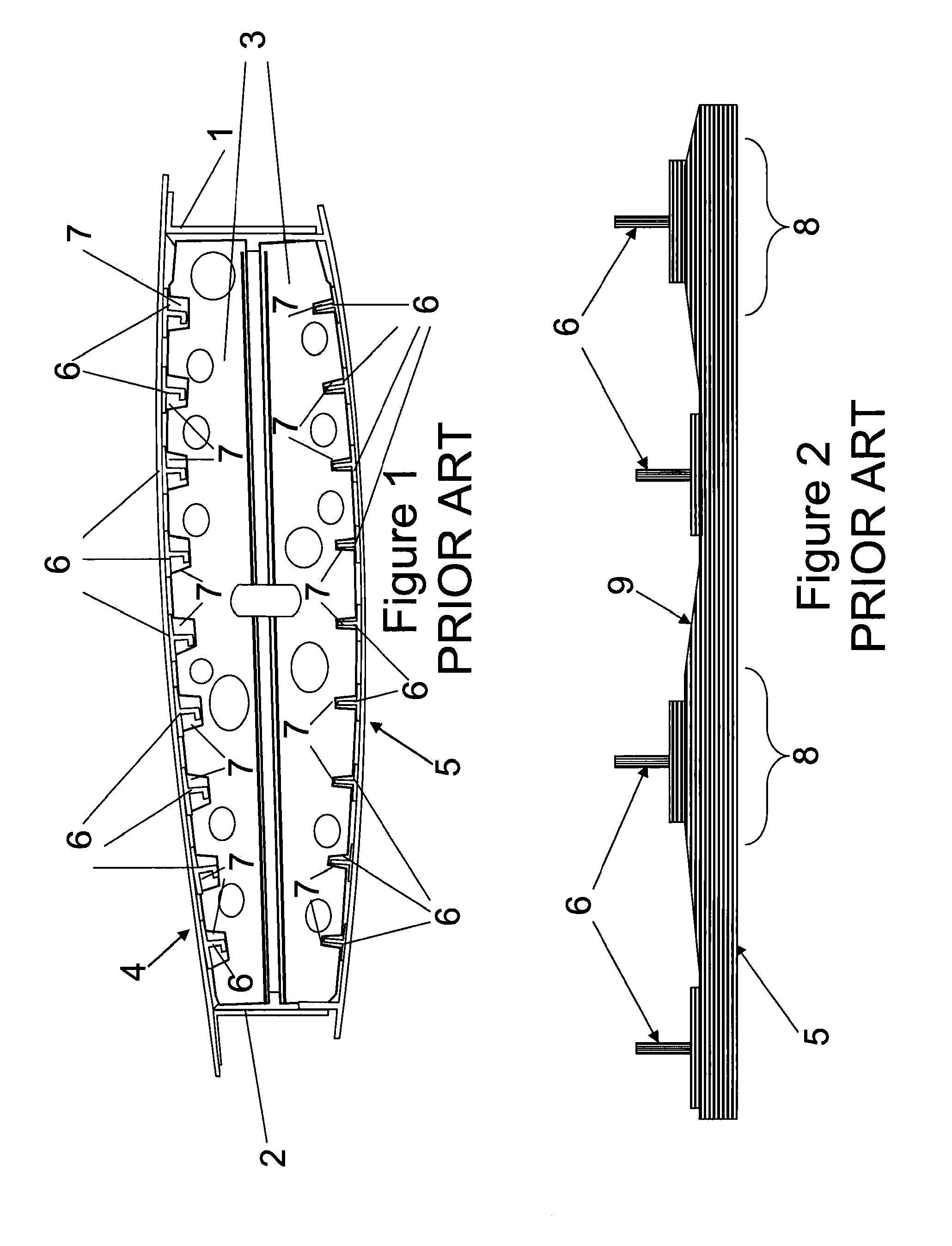
[0025]FIG. 1 shows a conventional aircraft wing box comprising a front spar 1, a rear spar 2, a two part chordwise rib 3, an upper wing cover 4 and a lower wing cover 5. The wing covers 4, 5 have a plurality of spanwise extending stringers 6 attached to, or integrally formed with, interior surfaces of the wing covers 4, 5. The rib 3 is attached to the covers 4, 5 by conventional rib feet (not shown). The rib 3 includes cut outs 7 to permit the stringers 6 to pass uninterrupted through the rib 3.

[0026]As will be appreciated by those skilled in the art, the wing of FIG. 1 has several of the chordwise ribs 3 spaced spanwise across the wing. Whilst the stringers 6 of the upper cover 4 are different to the stringers of the lower cover 5, this is purely a matter of design choice according to the loading requirements. Whilst a two part rib 3 is shown in FIG. 1, a single piece rib may alternatively be provided.

[0027]It is clear from FIG. 1 that the interface between the rib 3 and the inter...


PUM

PropertyMeasurementUnit
Thicknessaaaaaaaaaa

Abstract

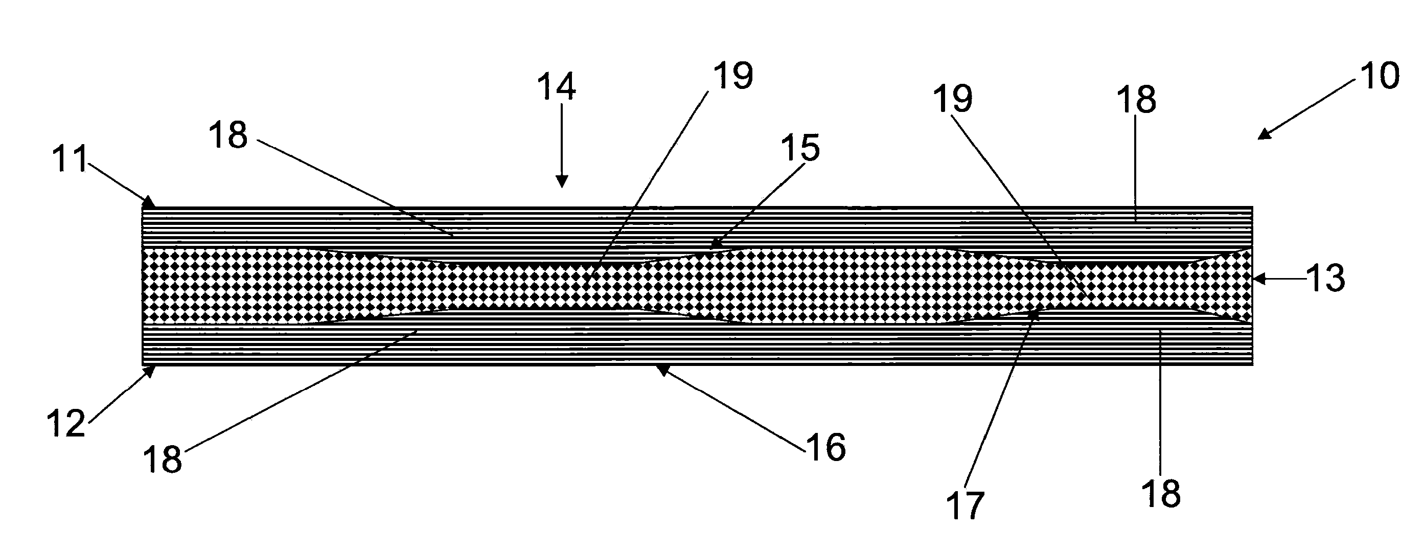
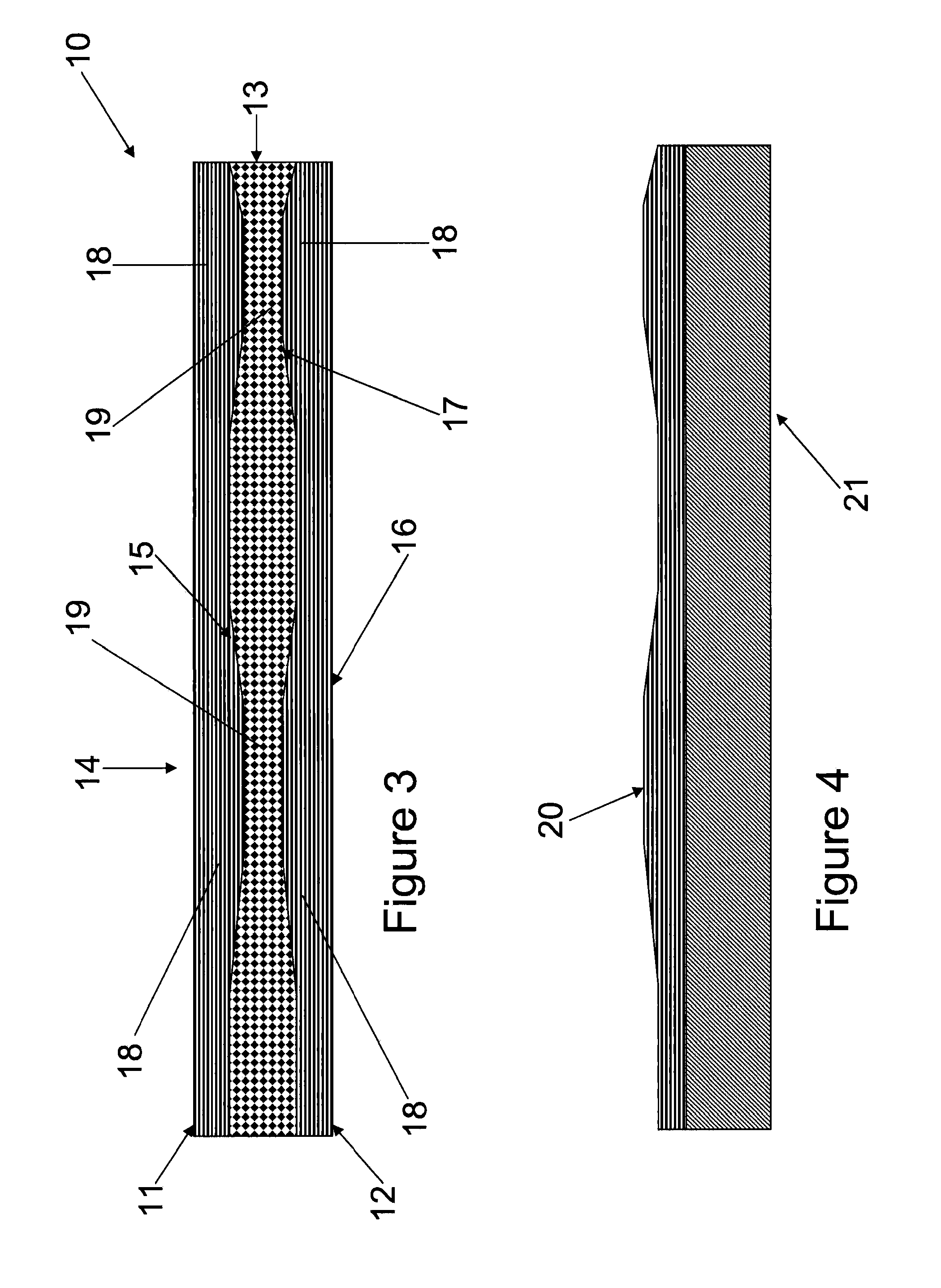
An aircraft wing cover (10) comprising an integrally stiffened sandwich panel including first and second skins (11, 12) sandwiching a core layer (13), wherein at least one of the skins has a plurality of spanwise extending integral regions of increased thickness (18) accommodated by corresponding regions (19) of decreased thickness in the core. Also, a method of fabricating an aircraft wing cover, and a method of designing an aircraft wing.

Description

FIELD OF THE INVENTION[0001]The present invention relates to an aircraft wing cover comprising a sandwich panel including first and second skins sandwiching a core layer. The invention also relates to an aircraft wing including the cover, a method of fabricating an aircraft wing cover, and a method of designing an aircraft wing.BACKGROUND OF THE INVENTION[0002]With the use of composite materials becoming more prevalent within the aircraft industry, it has become apparent that issues relating to the control of interfaces between components of large, complex, composite structures have become more of a challenge. In the case of an aircraft wing, the interfaces between wing spars, ribs and covers (skins) for a commercial airliner, for example, are particularly difficult to control. This is primarily due to the difficulty in controlling the through thickness tolerance associated with complex laminate composite components, especially when there are ramps (thickness variations) within thes...

Claims


Application Information

Patent Timeline
IPC IPC(8): B64C3/20
CPCB29C70/086B29C70/088B29C70/865B29C70/887B29D99/0021Y10T156/1074B29L2031/3085B29L2031/608B64C3/26B64C3/20Y02T50/433B29K2105/043Y02T50/40
Inventor PAYNE, CHRISTOPHERGRIGGS, PETERPEACOCK, ANTONY C.BULLOCK, RAYMONDWATSON, GLENN
Owner AIRBUS OPERATIONS LTD
Learn More