Power Supply System

a power supply system and power supply technology, applied in the field of power supply systems, can solve the problems of increasing the cost and size of the power supply system, affecting the reliability of the system, and affecting the reliability of the switching power supply, so as to improve the reliability. the effect of reliability

Active Publication Date: 2013-04-25
DENSO CORP
View PDF9 Cites 12 Cited by
  • Summary
  • Abstract
  • Description
  • Claims
  • Application Information

AI Technical Summary

Benefits of technology

[0011]An exemplary embodiment provides a power supply system which is able to enhance its reliability.

Problems solved by technology

Thus, reliability tends to be lower in a part of the switching power supplies than in other switching power supplies.
The techniques set forth above are able to enhance reliability of a power supply system but may have several inconveniences.
Therefore, the cost and size of the power supply system may be increased.
Therefore, for example, there is a concern that, in charging a battery with the switching power supplies, the battery is not necessarily appropriately charged.
It is difficult for other DC-DC converters to detect that the DC-DC converter in question is in a state of being limited in its output current by the specific value.
Accordingly, there is a concern that the specified value increasing unit is not able to timely increase the specified value.
Further, in this case, there is a concern that the output voltage of the DC-DC converters is drastically reduced.

Method used


Image

  • Power Supply System
  • Power Supply System
  • Power Supply System

Examples


Embodiment Construction

[0032]With reference to the accompanying drawings, hereinafter is described an embodiment of a power supply system of the present invention. In the embodiment, the power supply system of the present invention is applied to a large hybrid vehicle (e.g., bus) having a rotary machine and an engine as on-vehicle main machinery.

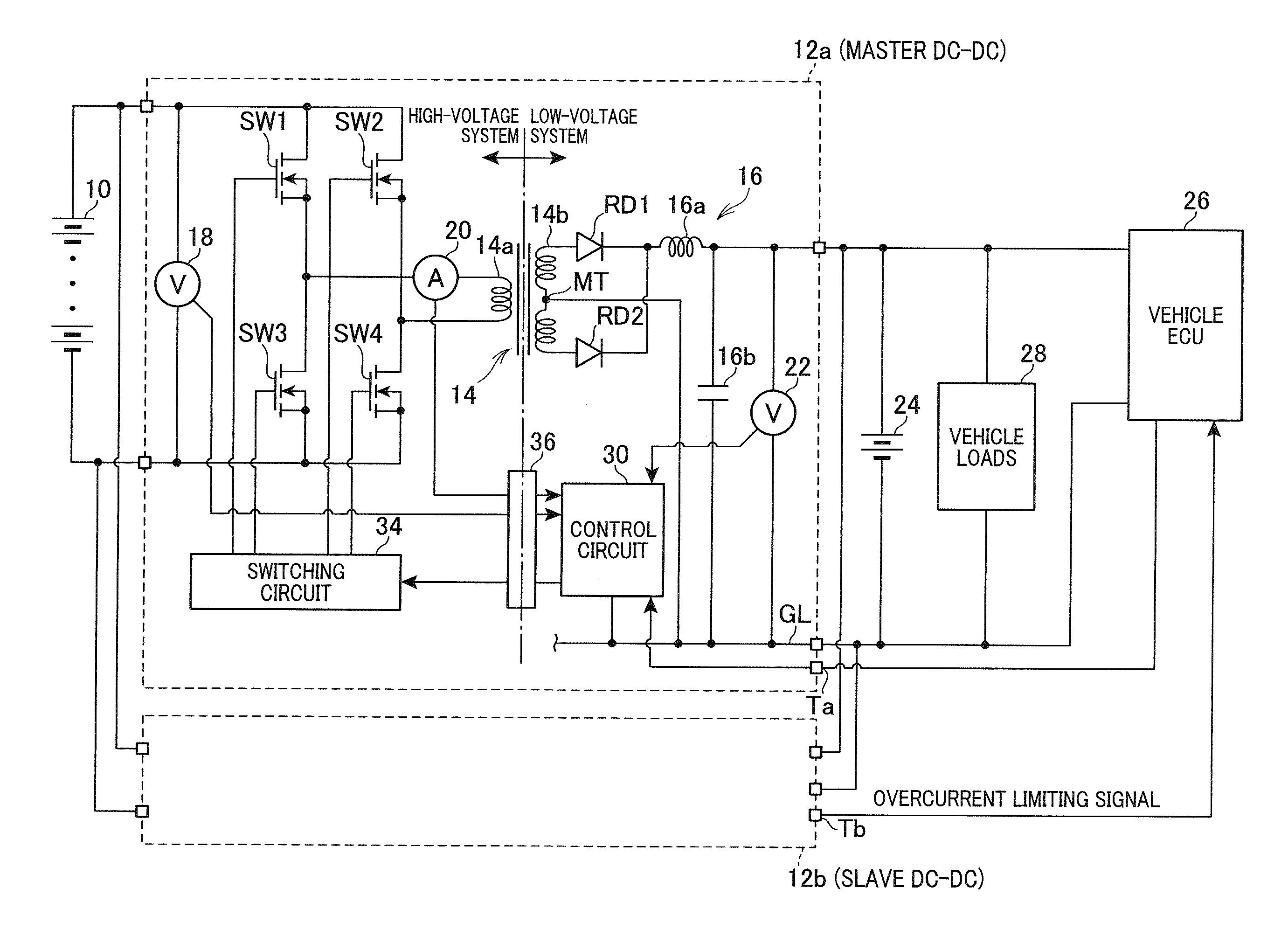
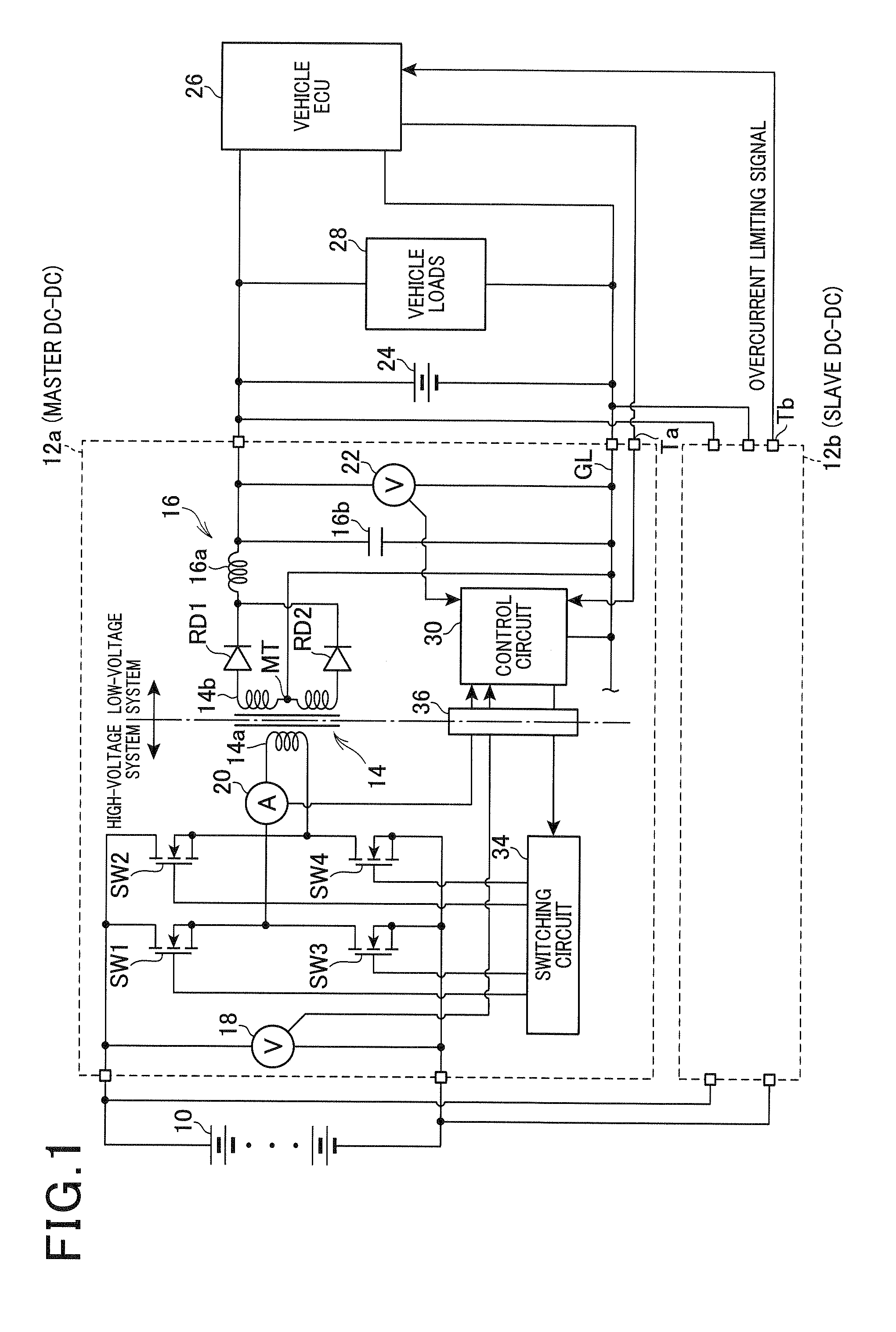
[0033]FIG. 1 is a schematic diagram illustrating a power supply system in general according to the embodiment.

[0034]As shown in FIG. 1, the power supply system includes a high-voltage battery 10. The high-voltage battery 10 serves as a power supply for a rotary machine (motor-generator), not shown, as on-vehicle main machinery. For example, the high-voltage battery 10 has a predetermined high voltage of several hundred volts or more. For example, a lithium-ion battery or a nickel-hydrogen battery is usable as the high-voltage battery 10.

[0035]The high-voltage battery 10 can be connected to each of a plurality of (two) DC-DC converters 12a and 12b which are connect...


PUM


Abstract

A power supply system includes a plurality of DC-DC converters and at least one operating unit. The DC-DC converters are connected in parallel to one another. The at least one operating unit operates the DC-DC converters such that power is supplied through the DC-DC converters to a predetermined power-supplied object. The at least one operating unit includes a voltage controller, a current limiter, and a specified value increasing unit. The voltage controller operates the DC-DC converters such that output voltages thereof are controlled to be respective target voltage. The current limiter operates the DC-DC converters such that output currents thereof are limited to respective specified value, when the output currents exceed the respective specified value. The specified value increasing unit increases the respective specified value for at least one of the DC-DC converters, when output current of the at least one of the DC-DC converters exceeds the specified value.

Description

CROSS-REFERENCE TO RELATED APPLICATION[0001]This application is based on and claims the benefit of priority from earlier Japanese Patent Application No. 2011-231322 filed Oct. 21, 2011, the description of which is incorporated herein by reference.BACKGROUND[0002]1. Technical Field[0003]The present invention relates to a power system including an operating unit which operates a plurality of DC (direct current) to DC converters (hereinafter referred to as DC-DC converters) connected in parallel to each other in such a way that power is supplied through the DC-DC converters to a predetermined power-supplied object.[0004]2. Related Art[0005]In a well-known power supply system, a plurality of switching power supplies (DC-DC converters) are connected in parallel to one another so as to supply power to a predetermined power-supplied object. The purpose of using this system is to increase a maximum current that can be supplied to the power-supplied object. In this system, current is outputt...

Claims


Application Information

Patent Timeline
Patent Type & Authority Applications(United States)
IPC IPC(8): H02M3/335
CPCH02M3/335H02J1/102H02M3/285
Inventor MACHI, TATSUYAKOMURA, HIROKIMISAWA, KATSUTOYOTANIGAWA, KEISUKE
Owner DENSO CORP
Why Eureka
Try Eureka