Flexible organic light emitting device and manufacturing method thereof

a light-emitting device and flexible technology, applied in the field of light-emitting devices, can solve the problems of inoperable and damaged flexible organic light-emitting devices, and achieve the effects of preventing the film layer from being absorbed by the organic light-emitting unit, facilitating the production of final products, and improving yield and device characteristics

Active Publication Date: 2013-04-25
AU OPTRONICS CORP
View PDF3 Cites 18 Cited by
  • Summary
  • Abstract
  • Description
  • Claims
  • Application Information

AI Technical Summary

Benefits of technology

[0009]According to a flexible organic light emitting device and a manufacturing method of a flexible organic light emitting device of the disclosure, the peeling of the film layer in the organic light emitting unit is prevented because the adhesive force between the insulation layer and the organic light emit unit is substantially less than 0.1 N / cm. In one exemplary embodiment, since the adhesive force between the insulation layer and the organic light emitting unit is substantially less than 0.1 N / cm and is substantially less than the adhesive force between the second electrode layer and the organic light emitting layer, peeling of the second electrode layer at the interface between the second electrode layer and the organic light emitting layer is thereby prevented. Accordingly, the flexible organic light emitting device of the disclosure provides a better yield and device characteristics.

Problems solved by technology

Consequently, peeling of a film layer in the organic light emitting device is resulted, and the flexible organic light-emitting device becomes damaged and inoperable.

Method used


Image

  • Flexible organic light emitting device and manufacturing method thereof
  • Flexible organic light emitting device and manufacturing method thereof
  • Flexible organic light emitting device and manufacturing method thereof

Examples


Embodiment Construction

[0014]Reference will now be made in detail embodiments of the invention examples of which are illustrated in the accompanying drawings.

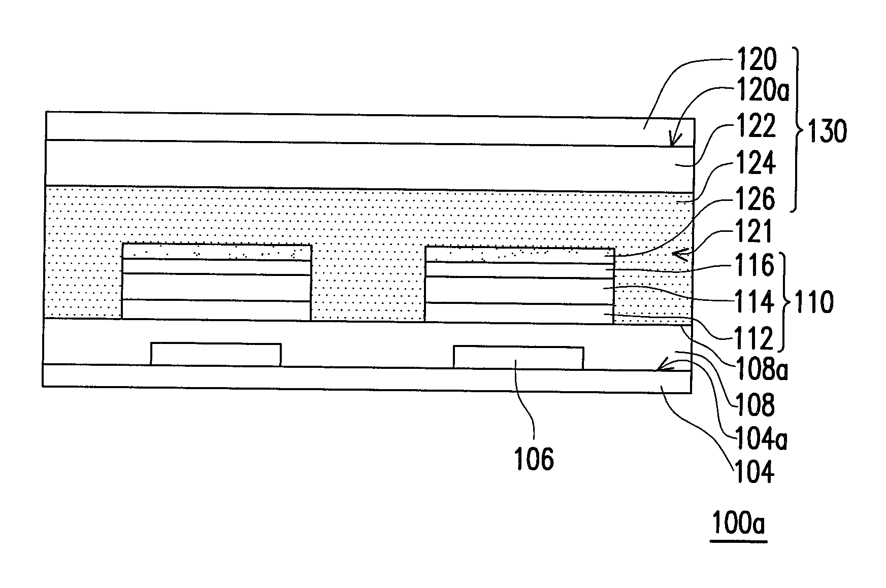
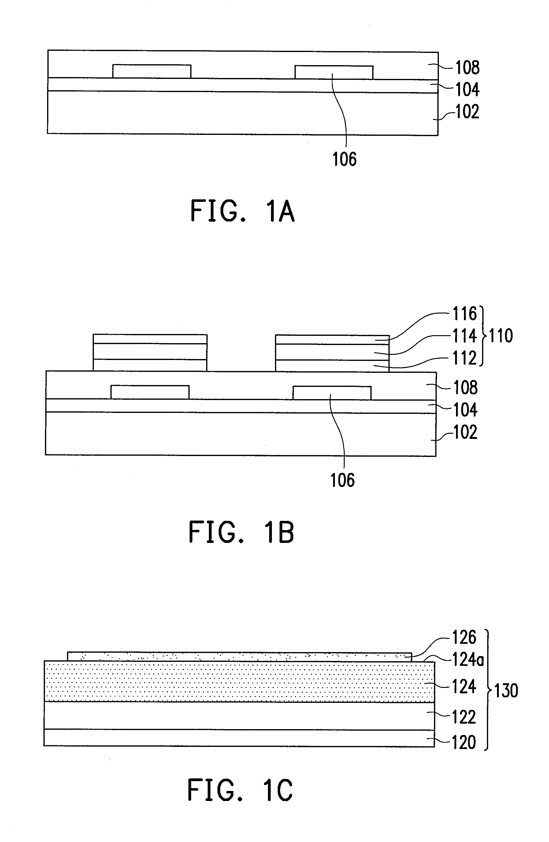
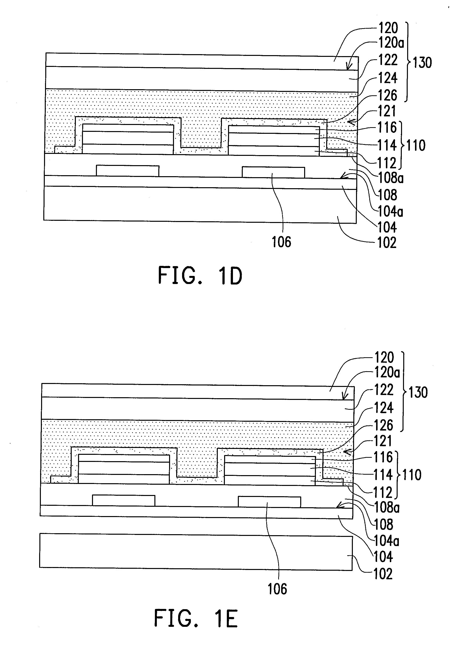
[0015]FIGS. 1A to 1F are schematic diagrams showing the steps for fabricating a flexible organic light-emitting device in a cross-sectional view according to an exemplary embodiment. The disclosure herein refers to certain illustrated embodiments exemplified with two organic light-emitting units, it is to be understood that these embodiments are presented by way of example and not by way of limitation. For example, it is understood by a person of ordinary skill practicing this invention that the light emitting device may include one organic light emitting unit or a plurality of organic light emitting units. In this exemplary embodiment, a flexible substrate 104 is first provided. The flexible substrate 104 is provided on a carrier substrate 102, for example. Also, in this exemplary embodiment, the carrier substrate 102 is a highly rigid substrate, su...


PUM


Abstract

A flexible organic light emitting device includes a flexible substrate, an organic light emitting unit and a covering substrate. The organic light emitting unit includes a first electrode layer, a second electrode layer opposing the first electrode, and a light emitting layer, which is disposed between the first and second electrode layers. The covering substrate includes a base film, an insulation layer and an adhesion layer. An inner surface of the base film is facing an inner surface of the flexible substrate, and space is formed there-between. The insulation layer is disposed on the inner surface of the base film, and an adhesive force between the insulation layer and the organic light emitting unit is less than 0.1 N/cm. The adhesion layer is disposed between the insulation layer and the inner surface of the base film, covers the insulation layer and the organic light emitting unit, and fills the space.

Description

CROSS-REFERENCE TO RELATED APPLICATION[0001]This application claims the priority benefit of Taiwan application serial no. 100138264, filed on Oct. 21, 2011. The entirety of the above-mentioned patent application is hereby incorporated by reference herein and made a part of this specification.BACKGROUND OF THE DISCLOSURE[0002]1. Field of the Disclosure[0003]This document relates to a light emitting device and a manufacturing method thereof, more particularly to a flexible organic light emitting device and a manufacturing method thereof.[0004]2. Description of the Related Art[0005]An organic light emitting device has the desirable qualities of light, compact, self-luminescent, low power consumption, back light-source free, and high reaction rate; therefore, it has been viewed as a dominant flat display device in the future. Moreover, an organic light emitting device can be configured in an array structure on a thin and flexible substrate; hence, it is suitably applied in illumination....

Claims


Application Information

Patent Timeline
Patent Type & Authority Applications(United States)
IPC IPC(8): H05B33/14H01J9/00
CPCH01L51/0097Y02E10/549H01L51/5253H01L51/524Y02P70/50H10K77/111H10K50/841H10K50/844
Inventor TSAI, CHIH-HUNGCHO, TING-YIWANG, CHUN-JANFANG, CHUN-HSIANG
Owner AU OPTRONICS CORP
Why Eureka
Try Eureka