

Rt-pcr chip with optical detection
- Summary
- Abstract
- Description
- Claims
- Application Information
AI Technical Summary
Benefits of technology
Problems solved by technology
Method used
Image

Examples
Embodiment Construction
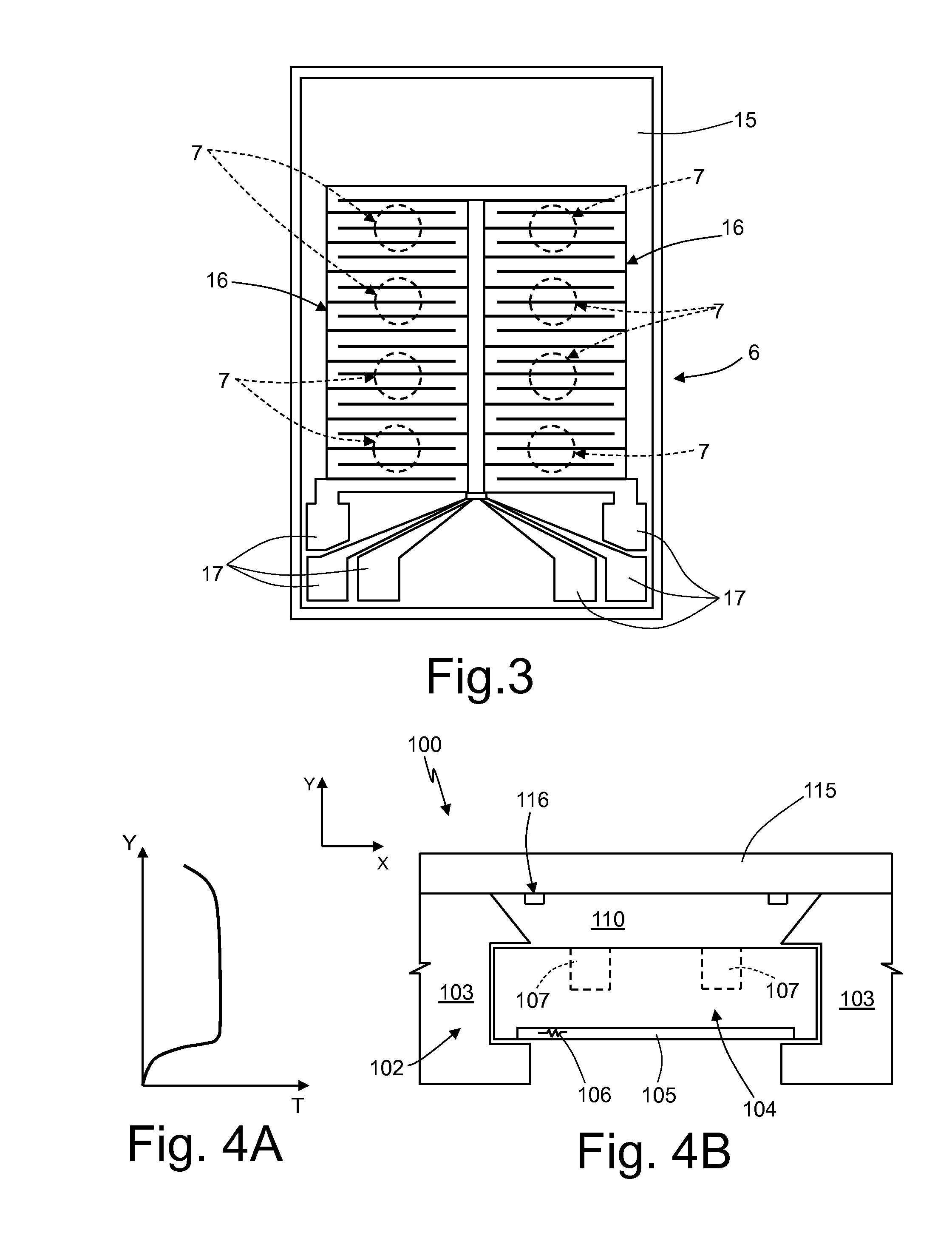
[0048]FIG. 4B shows a portion of an apparatus 100 for performing diagnostic analyses in order to detect the presence and amount of target molecules using the qRT-PCR technique referred to above. In particular, FIG. 4B shows a reaction zone 102 including guides 103 for a holder 104 similar to the one described with reference to FIGS. 1-2. In particular, the holder 104 has a first heating device 106 formed in a die 105 and forms a series of reaction chambers 107 (shown in ghost view and open on the top side) designed to contain the reagents and the reaction products and / or test-tubes. Alternatively, the first heating device 106 may be molded directly on the bottom or on a side of the holder 104.
[0049]The area above the holder 104 here forms a thermal chamber 110 closed at the top by a lid 115. The lid 115, of a generally rectangular shape, is transparent to the light of emitter elements 165 (FIG. 8) and to the fluorescent light emitted during the reaction so as to enable collection vi...
PUM
| Property | Measurement | Unit |
|---|---|---|
| Temperature | aaaaa | aaaaa |
| Current | aaaaa | aaaaa |
| Transparency | aaaaa | aaaaa |
Abstract
Description
Claims
Application Information