Thermoelectric conversion element and thermoelectric conversion device
a conversion element and thermoelectric technology, applied in the direction of thermoelectric device details, basic electric elements, electric devices, etc., can solve the problems of insufficient efficiency of the current seebeck effect elements, difficult to provide a uniform temperature gradient, and difficult to implement a thermoelectric conversion element that is industrially available, so as to achieve the effect of increasing the degree of freedom in the design of the elemen
- Summary
- Abstract
- Description
- Claims
- Application Information
AI Technical Summary
Benefits of technology
Problems solved by technology
Method used
Image
Examples
example 1
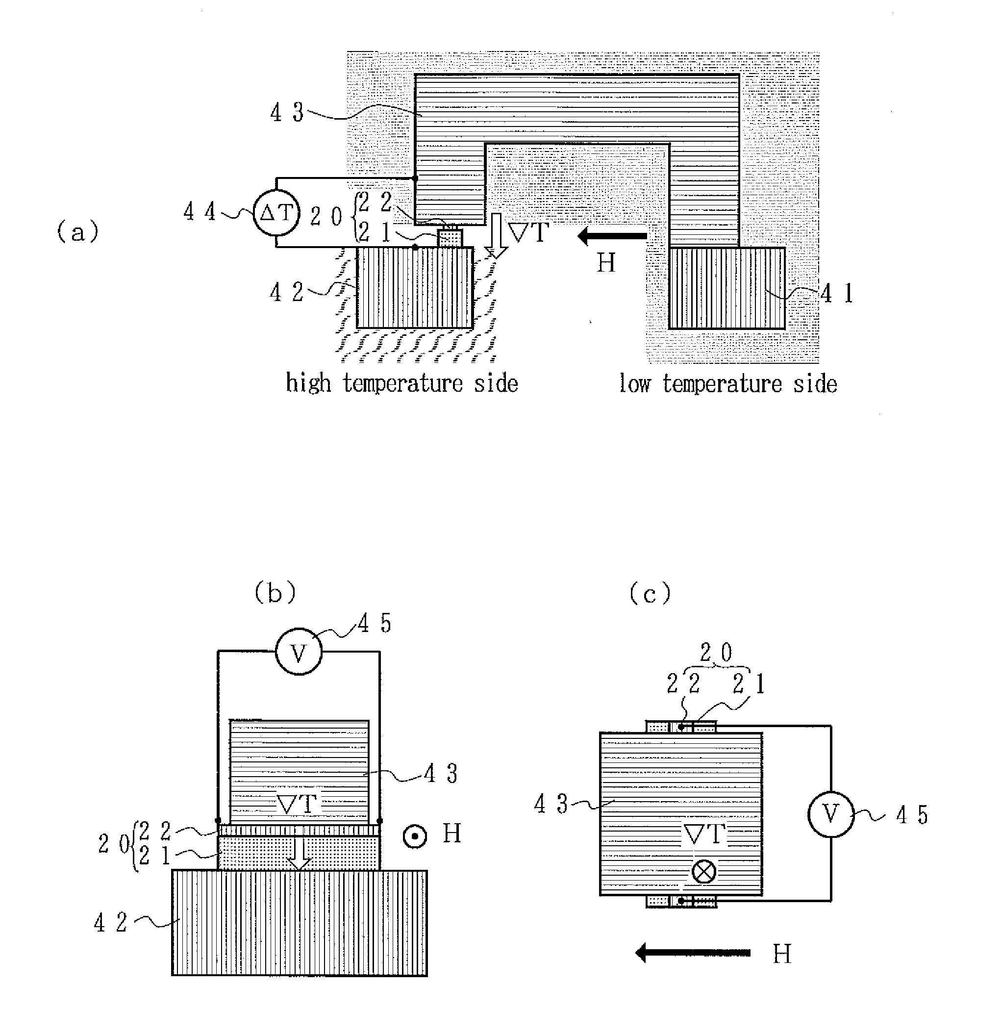
[0068]Here, the thermoelectric conversion device according to Example 1 of the present invention is described in reference to FIGS. 3(a) to 5(b). FIGS. 3(a) to 3(c) are diagrams showing the structure in the case where the Pt electrode side, which is the inverse spin Hall effect member side, is the high temperature side, where FIG. 3(a) is a schematic front diagram, FIG. 3(b) is a schematic side diagram, and FIG. 3(c) is a top diagram showing a main portion in the vicinity of the thermoelectric conversion element.
[0069]A thermoelectric conversion element 20 made of a single crystal YIG plate 21 and a Pt electrode 22 is secured to the top of a Cu block 41 and thermally connected to a Cu block 42 that makes contact with the heat source through a heat conveying member 43 in C shape made of brass. Thus, the temperature gradient ∇T is in the upward direction. Here, an external magnetic field H is applied in the direction perpendicular to the longitudinal direction of the Pt electrode and ...
example 2
[0074]Next, the thermoelectric conversion device according to Example 2 of the present invention is described in reference to FIGS. 6(a) and 6(b). FIGS. 6(a) and 6(b) are schematic diagrams showing the structure of the thermoelectric conversion device according to Example 2 of the present invention, where FIG. 6(a) is a schematic plan diagram and FIG. 6(b) is a schematic cross-sectional diagram along the single dotted chain line A-A′ in FIG. 6(a). A magnetized IrMn antiferromagnetic plate 23 is pasted to the rear surface of the YIG plate 21 of the above-described thermoelectric conversion element 20 made of a YIG plate 21 and a Pt electrode 22. At this time, the direction M of magnetization of the IrMn antiferromagnetic plate 23 is perpendicular to the longitudinal direction of the Pt electrode 22.
[0075]The same thermoelectric conversion elements as this thermoelectric conversion element 20 are alternately aligned on a flexible sheet 24, such as a PET sheet, so that the directions M...
example 3
[0077]Next, the thermoelectric conversion device according to Example 3 of the present invention is described in reference to FIGS. 7(a) and 7(b). FIGS. 7(a) and 7(b) are schematic diagrams showing the structure of the thermoelectric conversion device according to Example 3 of the present invention, where FIG. 7(a) is a schematic plan diagram and FIG. 7(b) is a schematic cross-sectional diagram along the single dotted chain line A-A in FIG. 7(a).
[0078]An IrMn antiferromagnetic layer 32 is deposited in lines with spaces in between on a heat-resistant flexible sheet 31, such as a heat-resistant glass fiber sheet, in accordance with a mask sputtering method. At this time, an external magnetic field is applied so that the IrMn antiferromagnetic layer 32 is magnetized in the direction of the external magnetic field.
[0079]Next, Fe3O4 is selectively deposited on the IrMn antiferromagnetic layer 32 in accordance with an aerosol deposition method so as to form a magneto-dielectric layer 33. ...
PUM
 Abstract
Description
Claims
Application Information
 - R&D
- Intellectual Property
- Life Sciences
- Materials
- Tech Scout
- Unparalleled Data Quality
- Higher Quality Content
- 60% Fewer Hallucinations
Browse by: Latest US Patents, China's latest patents, Technical Efficacy Thesaurus, Application Domain, Technology Topic, Popular Technical Reports.
© 2025 PatSnap. All rights reserved.Legal|Privacy policy|Modern Slavery Act Transparency Statement|Sitemap|About US| Contact US: help@patsnap.com


