Magnetic resonance imaging gradient coil, magnet assembly, and system

Active Publication Date: 2013-05-02
KONINKLIJKE PHILIPS ELECTRONICS NV
View PDF5 Cites 4 Cited by
  • Summary
  • Abstract
  • Description
  • Claims
  • Application Information

AI Technical Summary

Benefits of technology

[0027]In another embodiment the first and second gradient coil sections are electrically isolated. This embodiment is advantageous because this prevents mechanical energy by being transmitted by the connections between the first and second gradient coil sections.
[0028]In another embodiment the first and second gradient coil sections are connected electrically using bus bars. The bus bars are mounted elastically to the first and second rigid elements. This embodiment is advantageous because the first and second gradient coils can be connected electrically without acoustically coupling them. This may reduce the acoustic noise generated by the magnetic resonance imaging magnet assembly during operation.
[0029]In another embodiment the first and second gradient coil sections have separate cooling water connections and electrical power connections. That is to say that the coils which make up each of the first and second gradient coil sections are powered separately. For instance the z coil in the first gradient coil section may be connected to a gradient coil power supply and the z coil of the second gradient coil section may also be connected separately to the same or a different power supply. By having separate cooling water connections and electrical power connections the acoustic coupling between the first and second gradient coil sections may be reduced. This may have the benefit of r

Problems solved by technology

This leads to increased acoustic noise at particular operating frequencies.
Attempts to dampen resonances have been largely unsuccessful, because the entire structure is optimized to withstand large Lorentz forces without mechanical failure.
For example in U.S. Pat. No. 5,764,059 column 10 lines 20 through 21 it is written: “Thus contrary to intuition, a light coupling structure of high strength is required.”

Method used


Image

  • Magnetic resonance imaging gradient coil, magnet assembly, and system
  • Magnetic resonance imaging gradient coil, magnet assembly, and system
  • Magnetic resonance imaging gradient coil, magnet assembly, and system

Examples


Embodiment Construction

[0044]Like numbered elements in these figures are either equivalent elements or perform the same function. Elements which have been discussed previously will not necessarily be discussed in later figures if the function is equivalent.

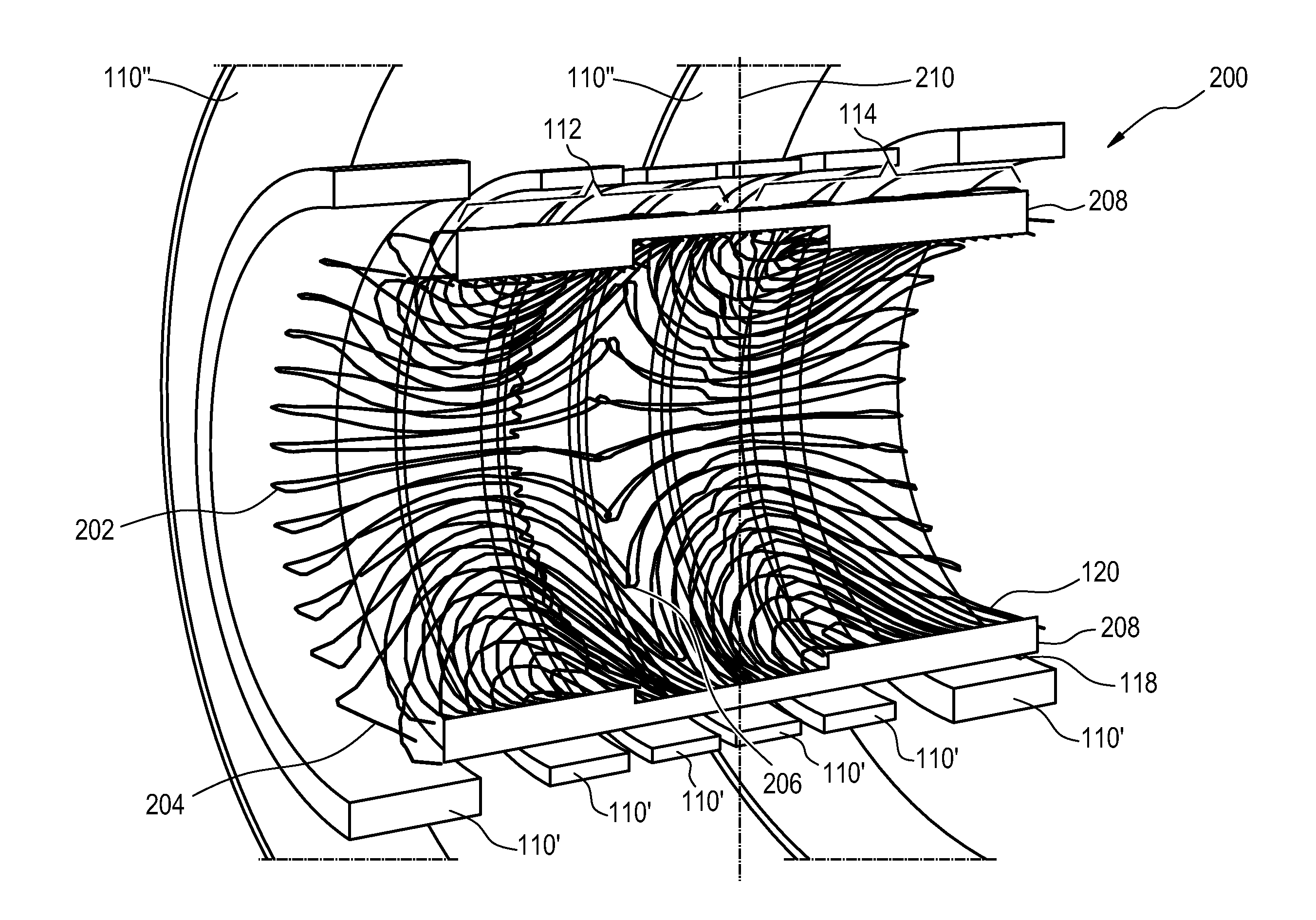
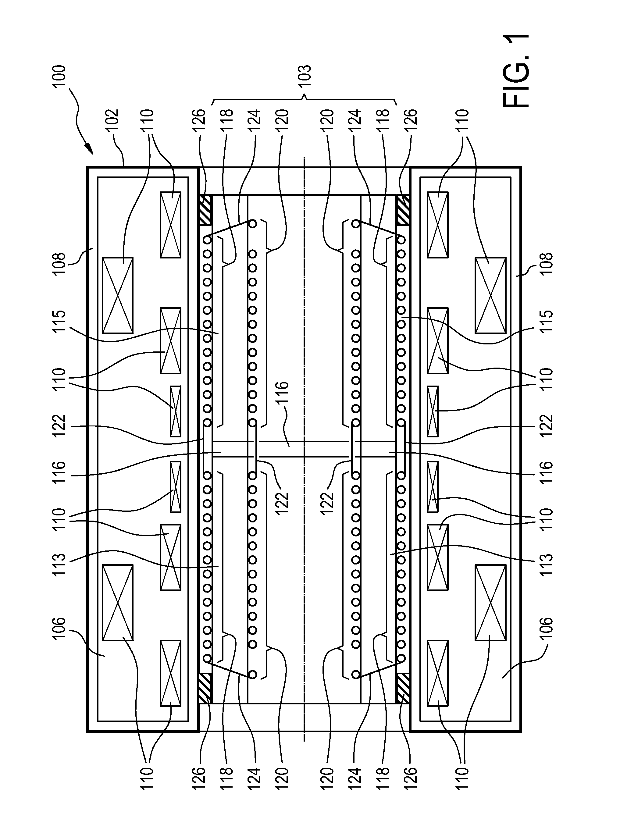
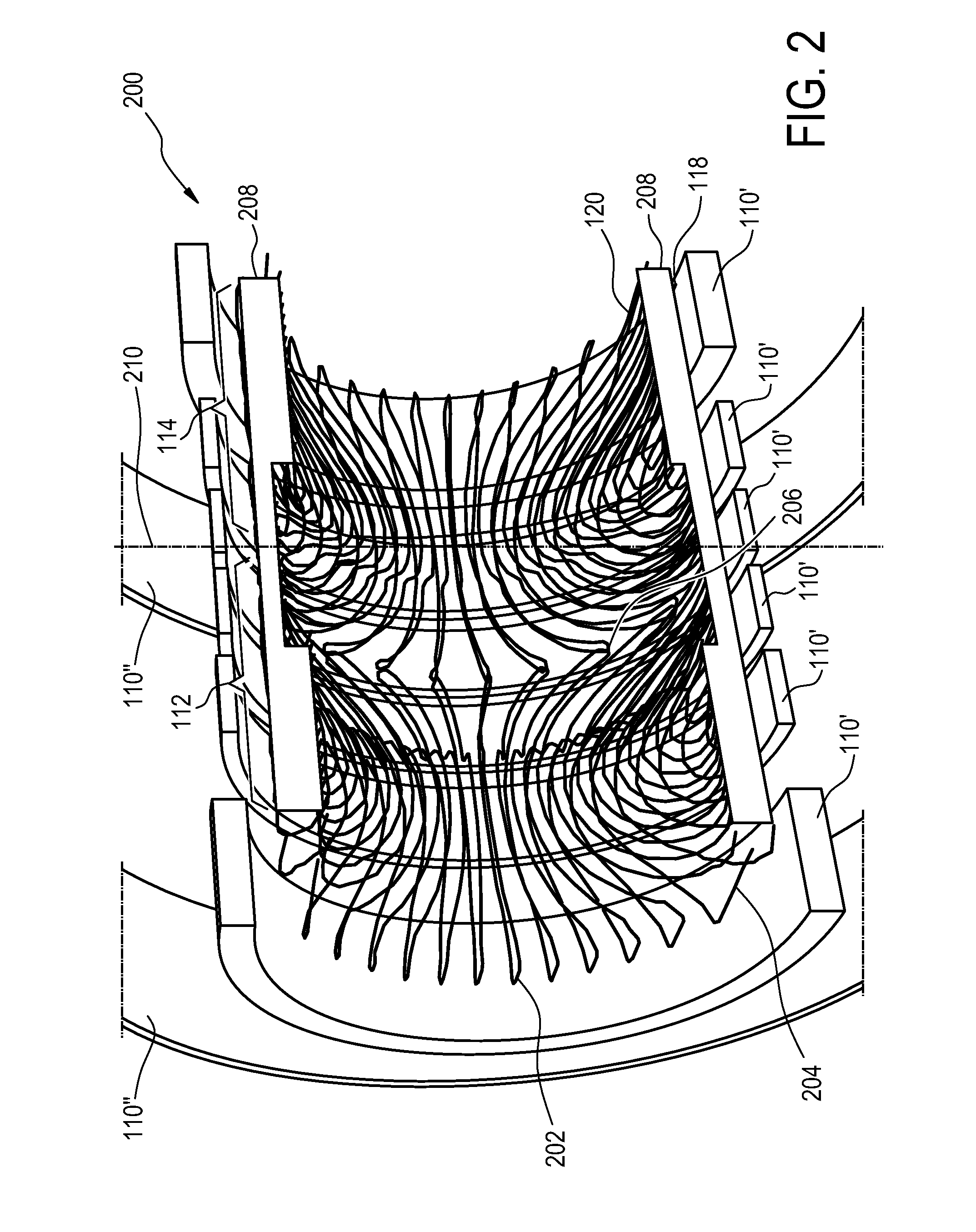
[0045]FIG. 1 shows a cross-sectional view of a magnetic resonance imaging magnet assembly 100 according to an embodiment of the invention. The magnet assembly 100 comprises a magnet 102 and a gradient coil 103. The magnet 102 shown in this Fig. is a magnet with a cylindrical symmetry. The axis of symmetry 104 of the magnet 102 is shown. The magnet 102 comprises a cryostat 106. The cryostat 106 is surrounded by an insulation system which may comprise a vacuum 108. The insulation system may also comprise a liquid nitrogen tank or vessel. Inside the cryostat 106 are superconducting coils 110.

[0046]The gradient coil 103 comprises a first gradient coil section 112 and a second gradient coil section 114. The first gradient coil section 112 and the second grad...


PUM


Abstract

A magnetic resonance imaging magnet assembly (100) comprising: a magnet (102) adapted for generating a main magnetic field for aligning the magnetic spins of nuclei of a subject (502) located within an imaging volume (504); and a gradient coil (103) for generating a gradient magnetic field for spatial encoding of the magnetic resonance signal of spins of nuclei within the imaging volume, wherein the gradient coil is adapted to be mounted into the magnet, wherein the gradient coil comprises: a first gradient coil section (112), wherein the first gradient coil section comprises a first rigid element (113), a second gradient coil section (114), wherein the second gradient coil section also comprises a second rigid element (115), a connecting element (116, 300, 302, 304, 400) for joining the two half gradient coils, wherein the connecting element comprises an elastic material (116), wherein the elastic material is in contact with the first rigid element and the second rigid element.

Description

TECHNICAL FIELD[0001]The invention relates to magnetic resonance imaging systems, in particular to the design of gradient coils for such systems.BACKGROUND OF THE INVENTION[0002]A static magnetic field is used by Magnetic Resonance Imaging (MRI) system to align the nuclear spins of atoms as part of the procedure for producing images within a subject. This static magnetic field is referred to as the B0 field or the main field.[0003]Magnetic field gradient coils are used to generate spatially and temporally variying magnetic fields which are used to spatially encode the nuclear spins being imaged. This spatial encoding is part of what allows the reconstruction of images from magnetic resonance imaging signals.[0004]However Magnetic Resoance Imaging is typically performed in a large magnetic field. As current flows through a magnetic field gradient coil the Lorentz force on the coil may be enormous. Gradient coils are typically mounted on or embedded within a rigid carrier to which the...

Claims


Application Information

Patent Timeline
IPC IPC(8): G01R33/385
CPCG01R33/3854G01R33/385G01R33/4215
Inventor OVERWEG, JOHANNES ADRIANUS
Owner KONINKLIJKE PHILIPS ELECTRONICS NV
Why Eureka
Try Eureka