

DC to DC convertor
- Summary
- Abstract
- Description
- Claims
- Application Information
AI Technical Summary
Benefits of technology
Problems solved by technology
Method used
Image

Examples
first embodiment
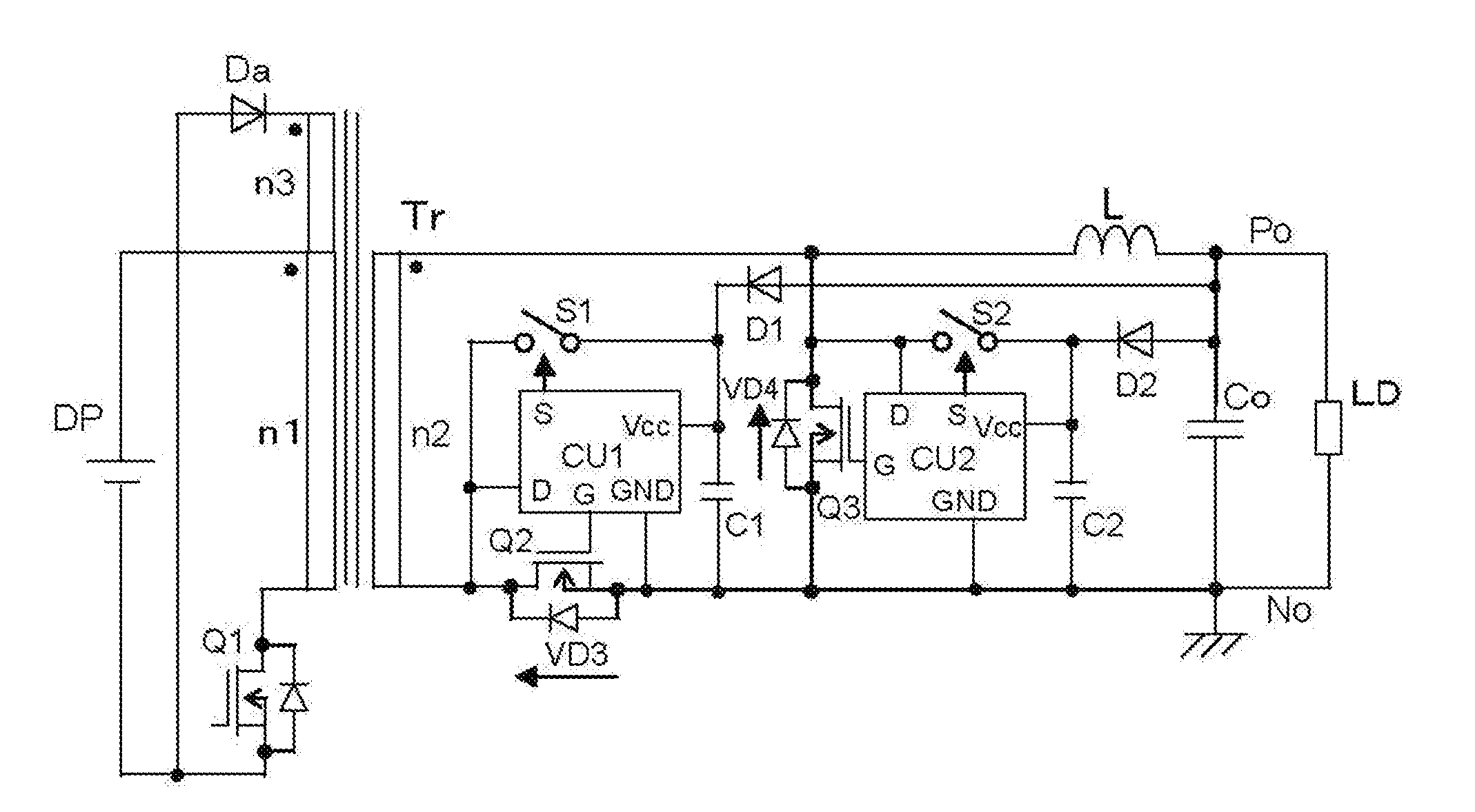
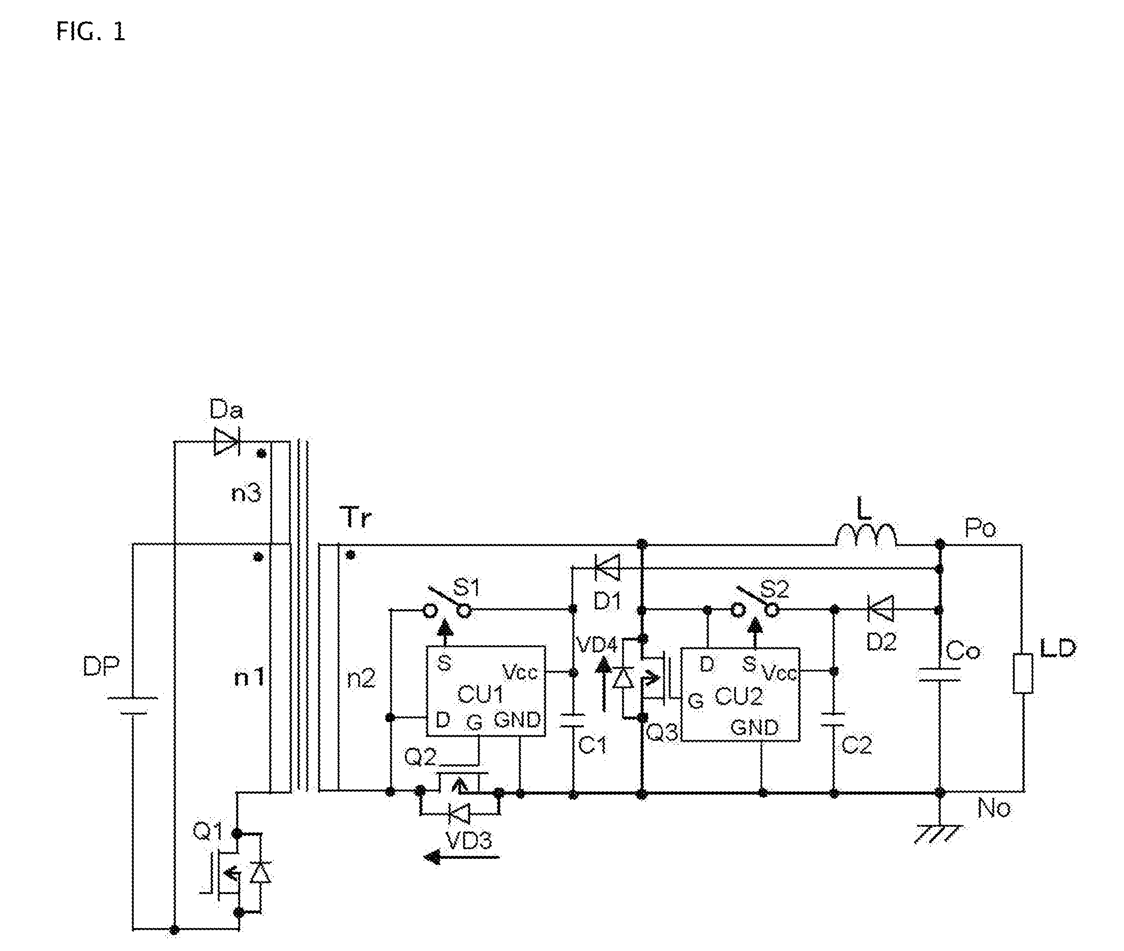
[0032]FIG. 1 shows a DC to DC converter of a first embodiment according to the invention. This converter of the first embodiment comprises a forward type DC to DC conversion circuit that includes a synchronously rectifying semiconductor switch for rectification and a synchronously rectifying semiconductor switch for free-wheeling. The converter of the first embodiment shown in FIG. 1 comprises a transformer Tr, a MOSFET Q2, a MOSFET Q3, a reactor L, and a smoothing capacitor Co. The primary winding n1 of the transformer Tr is driven by a DC power supply DP and a semiconductor switch, a MOSFET Q1. The magnetic energy stored in the transformer Tr during the ON period of the MOSFET Q1 is reset during the OFF period of the MOSFET Q1 with a tertiary winding n3 and a diode Da. One terminal of the secondary winding n2 of the transformer Tr is connected to one terminal of the reactor L; the other terminal of the secondary winding n2 is connected to the drain terminal of the MOSFET Q2 for re...
second embodiment
[0037]FIG. 4 shows a DC to DC converter of a second embodiment according to the invention. In the converter of the first embodiment described above, each of the MOSFET Q2 for rectification and the MOSFET Q3 for free-wheeling is connected to a snubber circuit composed of series-connected reverse-blocking semiconductor switch and a capacitor. In this second embodiment, however, a single capacitor Cs is used in common in both the snubber circuits. And only one controlling and driving unit CU5 is provided. A series-connected circuit of a reverse-blocking semiconductor switch S1 and the capacitor Cs is connected to the drain terminal and the source terminal of the rectifying MOSFET Q2. A reverse-blocking semiconductor switch S2 is connected between the drain terminal of a free-wheeling MOSFET Q3 and the connection point between the reverse-blocking semiconductor switch S1 and the capacitor Cs. A diode D1 is connected between the connection point between the reverse-blocking semiconductor...
third embodiment
[0039]FIG. 5 shows a DC to DC converter of a third embodiment according to the invention. This converter comprises, in addition to the circuit construction of the first embodiment of FIG. 1, a series-connected circuit of a semiconductor switch S3 and a resistor R1 provided in parallel with the capacitor C1 and a series-connected circuit of a semiconductor switch S4 and a resistor R2 provided in parallel with the capacitor C2. This featured additional structure can be used in the converter of the second embodiment and the converter of the fourth embodiment, which will be described later. FIGS. 6A and 6B illustrate control operation of the converter of FIG. 5, in which FIG. 6A is a detailed circuit diagram of a part of the converter and FIG. 6B shows operational waveforms. The operation about the semiconductor switch S3 is solely described in the following because the operation about the semiconductor switch S4 is same as that of the switch S3.
[0040]On the voltage VD3 across the recti...
PUM
 Abstract
Description
Claims
Application Information