Polarization maintaining multi-core optical fiber

a multi-core, optical fiber technology, applied in the direction of optical fibers with polarisation, optical waveguide light guides, instruments, etc., can solve the problems of insufficient reduction of fiber diameter, inability to investigate crosstalk among cores, and large stress-applying parts size, etc., to achieve effective crosstalk among cores, reduce overlap of field distribution, and increase density

Inactive Publication Date: 2013-05-02
SUMITOMO ELECTRIC IND LTD
View PDF6 Cites 240 Cited by
  • Summary
  • Abstract
  • Description
  • Claims
  • Application Information

AI Technical Summary

Benefits of technology

The present invention provides a polarization maintaining multi-core optical fiber that achieves high-density arrangement of cores and fiber diameter reduction while suppressing crosstalk among cores. Structural birefringence is generated resulting from structural asymmetry of each core or structural asymmetry in the vicinity of each core in a cladding, and it becomes possible to make it propagate with the polarization state maintained. The direction of the straight line connecting between the center of the arbitrary core and the center of the core nearest to the arbitrary core is different from a long axis direction of the field distribution of light in the arbitrary core. This reduces overlap of field distribution and crosstalk among cores. The arbitrary core is designed as an elliptic core or has a pair of holes arranged so as to sandwich the arbitrary core among the plural cores, which also generates birefringence. This allows for high-density arrangement of cores with reduced crosstalk.

Problems solved by technology

That is, in the polarization maintaining multi-core optical fiber of Patent Document 1 described above, there has been a problem that fiber diameter reduction cannot be performed sufficiently.
The reason is that for causing a birefringence in a core, it is necessary to secure a stress-applying part which is sufficiently larger than the core and that there is a possibility that a size of this stress-applying part poses a problem for high-density arrangement of cores and fiber diameter reduction.
In addition, generation of a crosstalk among cores has been often a problem in the past in a multi-core optical fiber, but in the polarization maintaining multi-core optical fiber according to Patent Document 1 described above, investigation on the crosstalk among cores has not been performed.
Therefore, in the conventional polarization maintaining multi-core optical fiber, there has been a possibility that suppression of the crosstalk among cores is insufficient.

Method used


Image

  • Polarization maintaining multi-core optical fiber
  • Polarization maintaining multi-core optical fiber
  • Polarization maintaining multi-core optical fiber

Examples


first embodiment

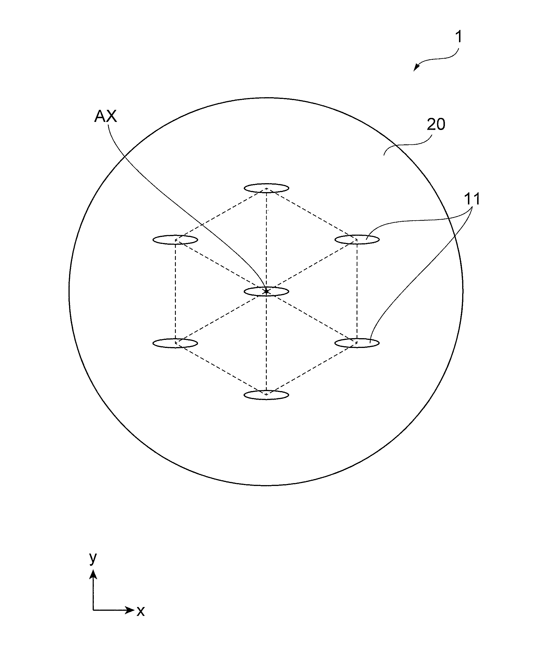
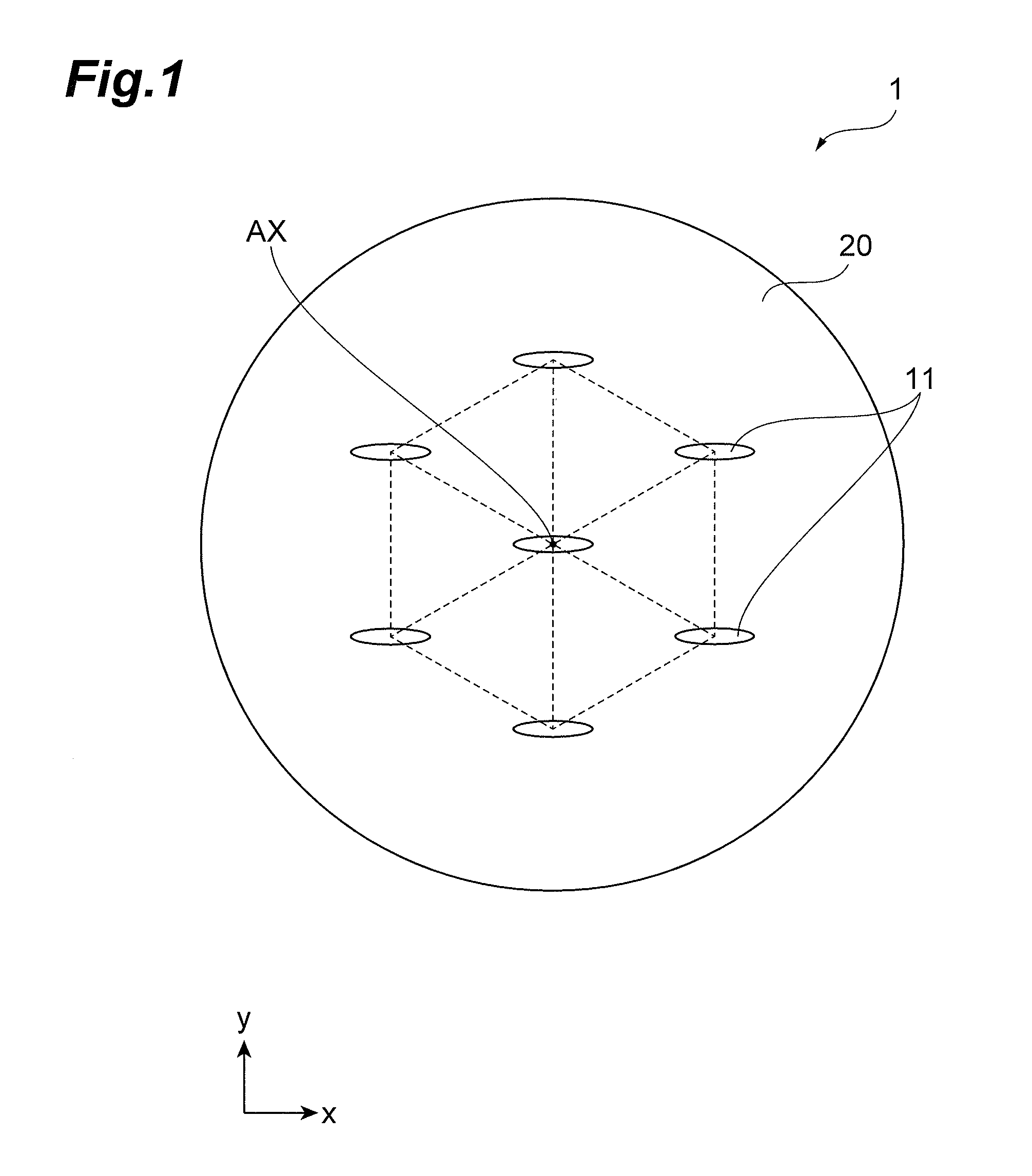
[0023]FIG. 1 is a schematic sectional view for showing a configuration of the polarization maintaining multi-core optical fiber according to a first embodiment of the present invention.

[0024]In a polarization maintaining multi-core optical fiber 1 according to the first embodiment, seven elliptic cores 11 each having an elliptic shape are provided in a cladding 20 via a part of the cladding 20. These seven elliptic cores 11 are arranged so that each center may correspond to a triangular lattice point. More specifically, the center core of the seven elliptic cores 11 is provided at the position where the center thereof becomes the center of the multi-core optical fiber 1, and is the nearest to six peripheral cores. Two cores among the six peripheral cores are arranged along the y-axis direction at the position which is in alignment with the center core, and each of four remaining cores or each of peripheral cores becomes the nearest to the peripheral cores adjacent thereto and the ce...

second embodiment

[0031]FIG. 3 is a schematic sectional view for showing a configuration of a polarization maintaining multi-core optical fiber according to a second embodiment of the present invention.

[0032]In a polarization maintaining multi-core optical fiber 3 according to the second embodiment, in the same way as the polarization maintaining multi-core optical fiber 1 according to the first embodiment, seven circular cores 12 are arranged so that the centers thereof may form triangular lattice points. Arrangement of circular cores 12 is the same as the arrangement of the elliptic cores 12 of the polarization maintaining multi-core optical fiber 1 according to the first embodiment, and the line connecting between the nearest cores has extended in the y-axis direction or in the direction where the angle formed with the y-axis will be 60 degrees. Then, at both sides of each circular core 12, one pair of side tunnels 31 which are made up of holes is provided. The side tunnel 31 and the circular core...

third embodiment

[0036]FIG. 4 is a schematic sectional view for showing a configuration of a polarization maintaining multi-core optical fiber according to a third embodiment of the present invention.

[0037]In the polarization maintaining multi-core optical fiber 3 described in the second embodiment, the side tunnel 31 has been arranged in the y-axis direction as shown in FIG. 3, but if this is arranged in the x-axis direction, a combination where the direction of the line connecting between the centers of the nearest cores and the long axis direction of the field distribution will have been in agreement will be generated in some cores (a case where cores which are adjacent in the y-axis direction are the nearest to each other), and as a result, an increase of the crosstalk among cores will be cared. As a method to solve this, considered is a method where the center distance of cores which are adjacent in the y-axis direction is made to be enlarged, and these cores are made not to be the nearest core...


PUM


Abstract

In a polarization maintaining multi-core optical fiber according to the present invention, structural birefringence is generated since an elliptic core is applied. In addition, each core is arranged so that a direction of a line connecting between centers of the nearest cores and a long axis direction of a field distribution in each core may be different from each other, and thereby, overlap of field distributions between the nearest cores is reduced. As a result, a crosstalk among cores is reduced.

Description

BACKGROUND OF THE INVENTION[0001]1. Field of the Invention[0002]The present invention relates to a polarization maintaining multi-core optical fiber.[0003]2. Related Background of the Invention[0004]Known is a polarization maintaining multi-core optical fiber which has a structure where while a plurality of cores is provided in a cladding, an intermediate layer (a stress-applying layer and / or a hole) for causing a birefringence in the cores is provided among the cores, and in which this intermediate layer is shared by a plurality of cores (refer to Japanese Patent Application Laid-Open No. 62-178909 (Patent Document 1), for example).SUMMARY OF THE INVENTION[0005]The present inventors have examined the above-described conventional polarization maintaining multi-core optical fiber, and as a result, have discovered the following problems.[0006]That is, in the polarization maintaining multi-core optical fiber of Patent Document 1 described above, there has been a problem that fiber diam...

Claims


Application Information

Patent Timeline
IPC IPC(8): G02B6/02
CPCG02B6/024G02B6/02042
Inventor SASAOKA, EISUKEKANAMORI, HIROO
Owner SUMITOMO ELECTRIC IND LTD
Why Eureka
Try Eureka