System for selectively proceeding a sample

a sample and sample technology, applied in the field of sample system, can solve the problems of increasing the number of possible assays, increasing the number of assays, so as to reduce the handling steps, increase the menu of assays, and reduce the effect of handling steps

Inactive Publication Date: 2013-05-02
KONINKLIJKE PHILIPS ELECTRONICS NV
View PDF1 Cites 16 Cited by
  • Summary
  • Abstract
  • Description
  • Claims
  • Application Information

AI Technical Summary

Benefits of technology

[0008]Due to its universal reagent reservoir, the described system has the advantage that the number of different reservoirs that have to be kept on stock is reduced, which facilitates the demands of available space and simplifies the handling steps that have to be done. At the same time, the sensitivity of the approach is guaranteed by the use of specific reservoirs, which can be loaded with those reagents the combination of which would impair the outcome of the assays. It turns out that the combination of universal and specific reagent reservoirs is optimally suited for a use in a high-throughput centralized laboratory environment.
[0045]Leaving the top side of the sample chamber accessible simplifies the production of the cartridge as no components like fluidic structures are needed and as chemicals like binding sites can more readily be applied to the (bottom) surface of the sample chamber. Moreover, the cartridge is more readily accessible for filling it with a sample and / or with reagents, and the filling is achieved quasi instantaneously (instead of slowly as if the fluid has to move along channels).

Problems solved by technology

a) A plurality of reagent reservoirs, called “specific reagent reservoirs” in the following, wherein said specific reagent reservoirs comprise different (individual) sets of reagents and wherein each of these sets is required for one (and preferably only one) of the assays. With other words, the reagents of one specific reagent reservoir are associated to one of the assays and are generally not suitable or needed for the other assays. It should be noted that a “set” of reagents may in the most simple case comprise just one reagent.

Method used


Image

  • System for selectively proceeding a sample
  • System for selectively proceeding a sample
  • System for selectively proceeding a sample

Examples


Embodiment Construction

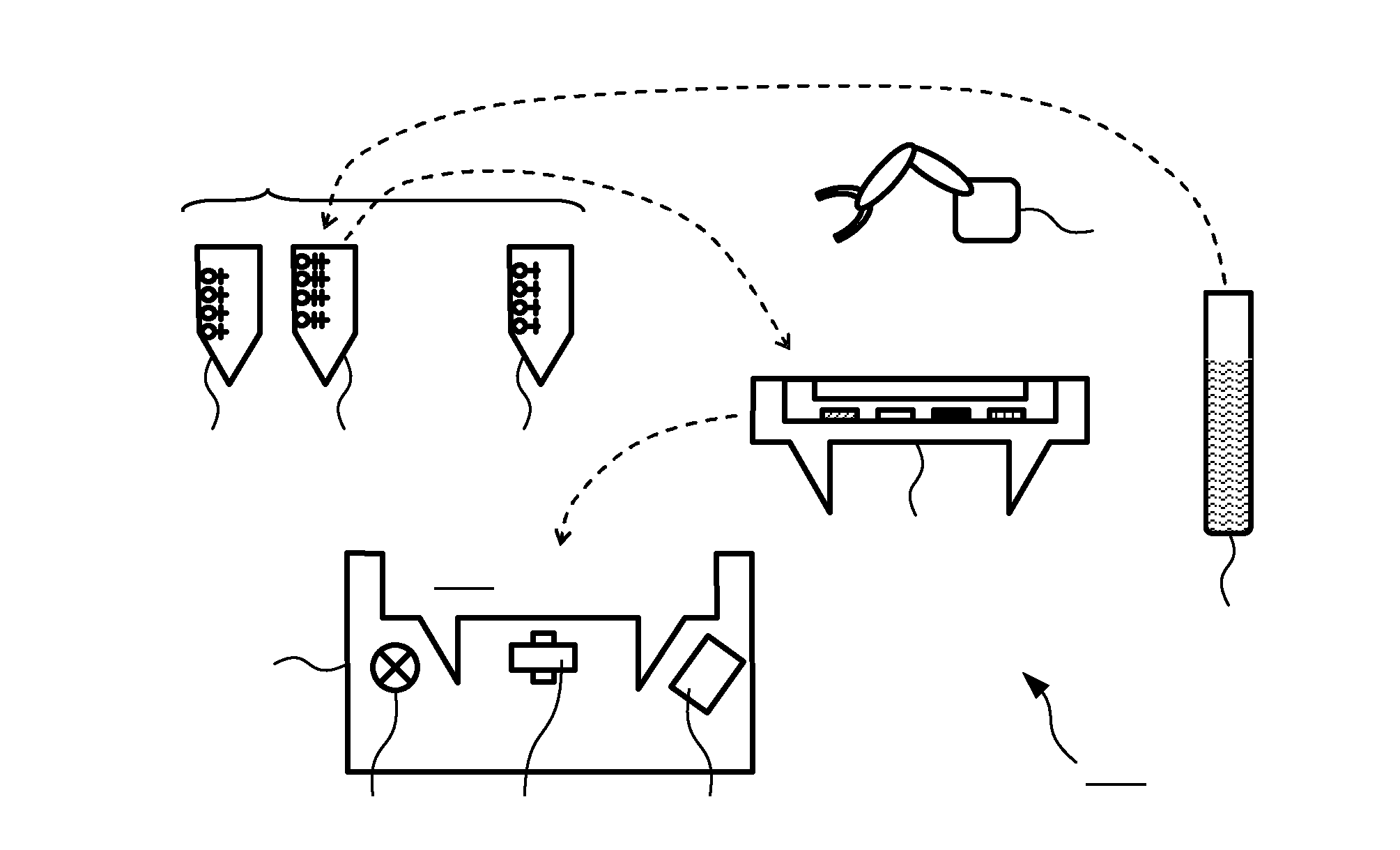
[0069]Biosensors based on nanoparticle labels, particularly nanoparticles that can be actuated with electromagnetic fields (“magnetic beads”), are for example know from the WO 2008 / 155716 A1. Typically, the magnetic beads are functionalized with antibodies that can bind a specific target molecule. The beads are attracted to the sensor surface, where the number of bound beads is directly or inversely related to the amount of target molecules present in the sample. The beads can then be detected using any technique that is more sensitive to beads that are close to the surface, e.g. frustrated total internal reflection (FTIR). Using this technique, the sensitivity to the nanoparticle labels decreases exponentially with an increasing distance from the surface. The described technology has been developed for point-of-care (POC) applications.

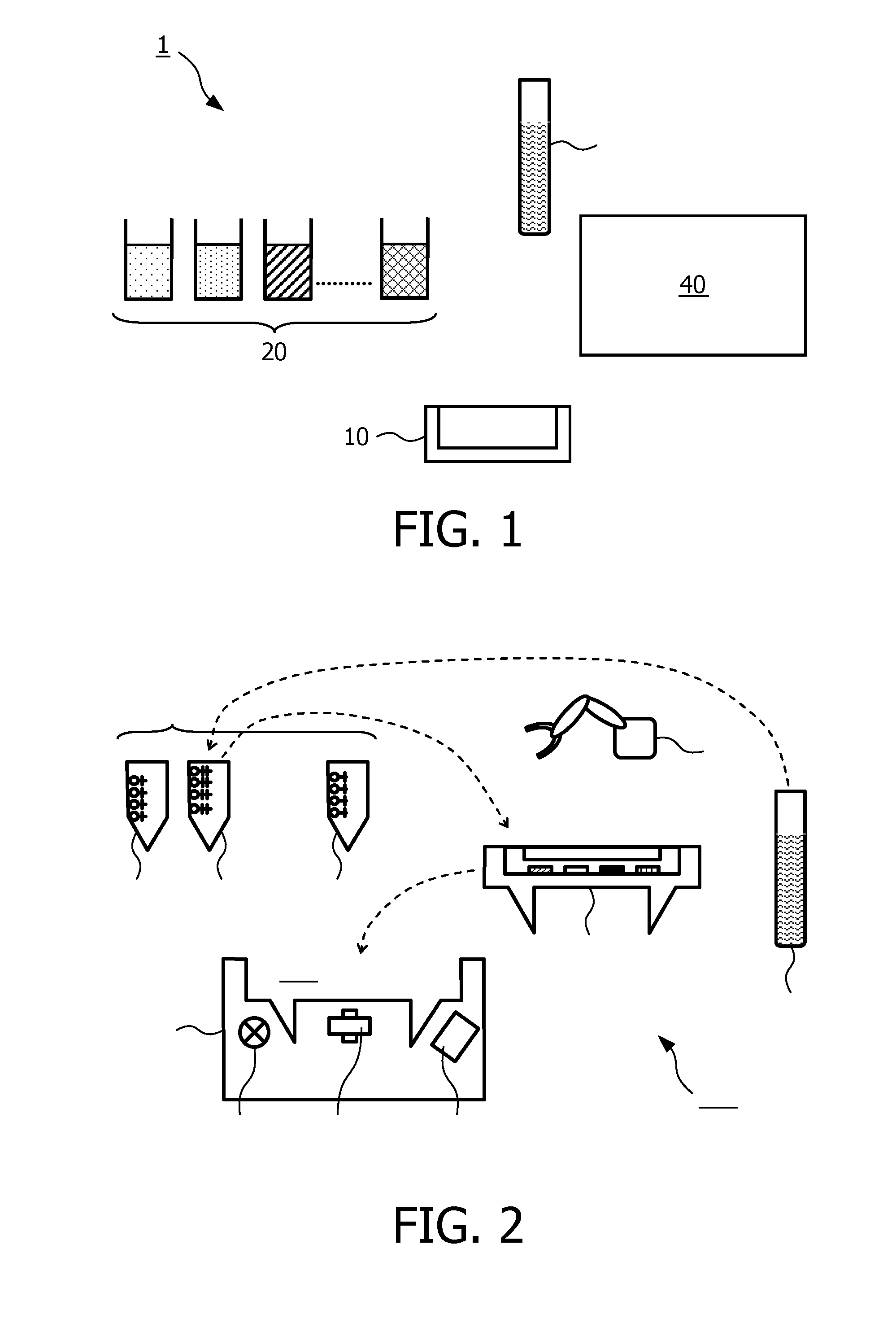
[0070]In contrast to this, the majority of immunoassay testing is carried out in central laboratories, where large instruments are used. FIG. 1 schem...


PUM

PropertyMeasurementUnit
electromagnetic fieldsaaaaaaaaaa
frustrated total internal reflectionaaaaaaaaaa
physicalaaaaaaaaaa

Abstract

The invention relates to a method and a system (100) for selectively processing a sample (130) according to one of a plurality of different assays, for example for detecting a certain target component in the sample. The system comprises a plurality of “specific reagent reservoirs” (120) that contain different sets of reagents, wherein each set is required for one of the assays. Moreover, the system (100) comprises a “universal reagent reservoir” in which reagents for several assays are provided, preferably reagents for all assays. The universal reagent reservoir may preferably be a cartridge (110) in which the processing of a sample (130) can take place and which comprises a plurality of binding sites that are selective for different target components. Depending on the assay to be performed with a sample (130) at hand, the appropriate specific reagent reservoir (121b) is chosen and processed in the universal cartridge (110). This can particularly be done by a manipulator (140) in a high-throughput automated laboratory system.

Description

FIELD OF THE INVENTION[0001]The invention relates to a system and a method for processing a sample according to a selected one of a plurality of assays, particularly for detecting selected target components in a biological sample. Moreover, it relates to designs of a pipette-tip and a cartridge that can be used in such a system.BACKGROUND OF THE INVENTION[0002]From the WO 2008 / 155716 A1 a biosensor is known in which target components labeled with magnetic beads are detected by frustrated total internal reflection (FTIR) at the sensing surface of a cartridge. The described biosensor is particularly designed and suited for point-of-care applications, for example roadside drug tests.SUMMARY OF THE INVENTION[0003]Based on this background it was an object of the present invention to provide means that allow the processing of a sample in a stationary, high-throughput laboratory environment.[0004]This object is achieved by a system according to claim 1, a method according to claim 2, a pip...

Claims


Application Information

Patent Timeline
Patent Type & Authority Applications(United States)
IPC IPC(8): G01N1/10
CPCB01L3/0275Y10T436/2575B01L7/52B01L2200/04B01L2200/0684B01L2200/16B01L2300/027B01L2300/044B01L2300/0627B01L2300/0654B01L2300/087B01L2400/043G01N35/00029G01N35/0098G01N35/1002G01N2035/00158G01N2035/0436G01N1/10B01L3/527
Inventor KLUNDER, DERK JAN WILFREDNIEUWEHUIS, JEROEN HANSPRINS, MENNO WILLEM JOSEEVERS, TOON HENDRIK
Owner KONINKLIJKE PHILIPS ELECTRONICS NV
Why Eureka
Try Eureka