Multiple-in-multiple-out antenna network-coded amplify-and-forward relaying scheme for three node bidirectional cooperation

a multi-in-multi-out antenna and bidirectional cooperation technology, applied in repeater/relay circuits, site diversity, transmission monitoring, etc., can solve problems such as the suffering of transmission between two nodes, and achieve high throughput (vht)

Active Publication Date: 2013-05-09
INTERDIGITAL MADISON PATENT HLDG
View PDF20 Cites 22 Cited by
  • Summary
  • Abstract
  • Description
  • Claims
  • Application Information

AI Technical Summary

Benefits of technology

[0013]The NCAF relaying scheme of the present invention, may prove to be essential to the future the IEEE 802.11 draft Very High Throughput (VHT) standard. The advantage of the NCAF relaying scheme of the present invention is that only simple processing, i.e., linear pre-coding, is needed at the relay node (RN). It is also...

Problems solved by technology

If the channel conditions between the nodes are inadeq...

Method used


Image

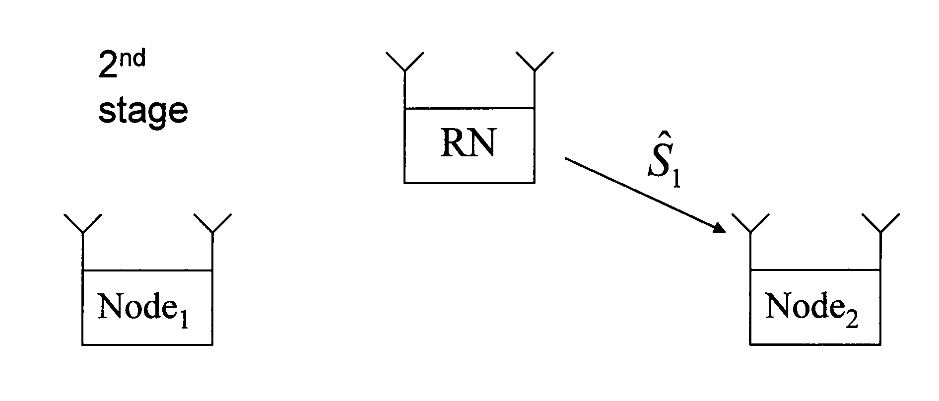
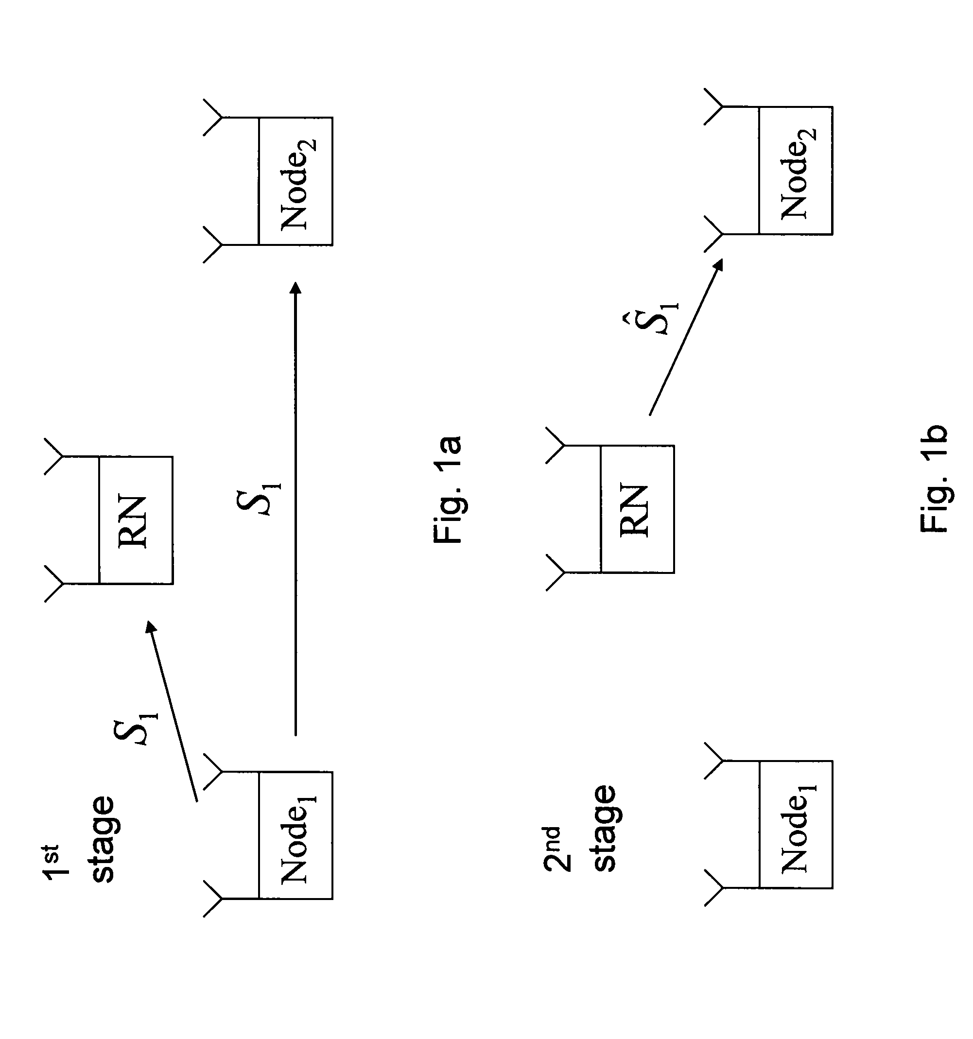
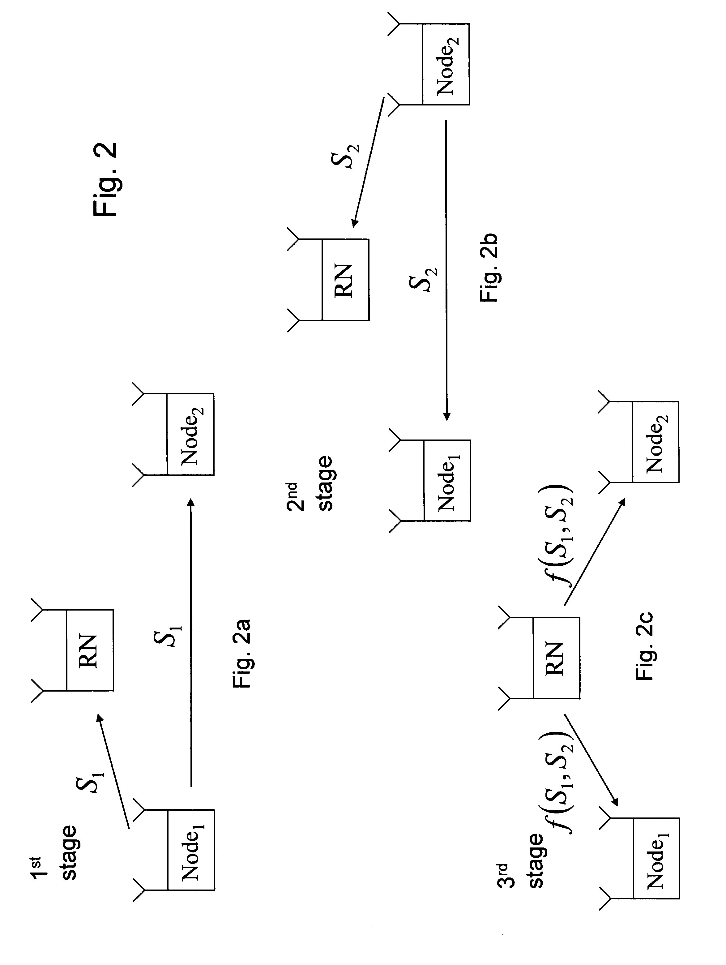
  • Multiple-in-multiple-out antenna network-coded amplify-and-forward relaying scheme for three node bidirectional cooperation
  • Multiple-in-multiple-out antenna network-coded amplify-and-forward relaying scheme for three node bidirectional cooperation
  • Multiple-in-multiple-out antenna network-coded amplify-and-forward relaying scheme for three node bidirectional cooperation

Examples


case 2

[0044]General When α1 and β2 exist, {tilde over (W)}1 is an identity matrix multiplied by a constant, i.e., {tilde over (W)}1=λ1ILR, λ1≧0; while {tilde over (W)}2=Λ21 / 2=diag{λ2, 11 / 2, . . . , λ2, LR1 / 2}. λ2, i≧0, i=1, . . . , LR, is a diagonal matrix. The notation in the iterative approach is as follows:

λ=(λ1,λ2,1,…,λ2,LR)T,max_λ=(PRdaσn2,PRcb,1σn2,L,PRcb,Mσn2,1LR-MT)T,μ=(μ1,L,μL2(L2-1)+1)T,vk=(vλ1k,vλ2,1k,L,vλ2,LRk,vμ1k,L,vμL2(L2-1)+1k)T,1N=(1,…,1N).S=[0L2(L2-1)×1S2dacb,1,L,cb,M,01×(LR-M)],q=(0L2(L2-1)×1PRσn2),whereca,i=P1L1σn2λR1,i+1,cb,i=P2L2σn2λR2,i+1,i=1,L,M,da=∑i=1Mca,i,andM=min(L1,L2,LR).

[0045]And

S2=[Re{s2}Im{s2}]∈RL2(L2-1)×LR,

where Re{•} and Im{•} are the functions which take the real and imaginary parts of the variables, and s2 comes from the linear equations

∑k=1LRλ2,ktki*tkj=0,1≤i<j≤L2,i.e.,s2=(t11*t12t21*t22LtLR,1*tLR,2t11*t13t21*t23LtLR,1*tLR,3MMOMt11*t1,L2t21*t2,L2LtLR,1*tLR,L2t12*t13t22*t23LtLR,2*tLR,3MMOMt12*t1,L2t22*t2,L2LtLR,2*tLR,L2MMOMt1,L2-1*t1,L2t2,L2-1*t2,L...

case 3

[0046]General When β1 and β2 exist, both W1%=Λ11 / 2=diag{λ1, 11 / 2}. λ1, i≧0, i=1, L, LR, and W2%=Λ21 / 2=diag{λ2, 11 / 2, L, λ2, LR1 / 2}, λ2, i≧0, i=1, L, LR, are diagonal matrices. The notation in the iterative approach is as follows:

λ=(λ1,1,Lλ1,NR,λ2,1,Lλ2,LR)T,μ=(μ1,L,μL2(L2-1)+1)T,max_λ=(PRca,1σn2,L,PRca,Mσn2,1LR-MT,PRcb,1σn2,L,PRcb,Mσn2,1LR-MT)T,1N=(1,…N,1),andvk=(vλ1,1k,L,vλ1,LRk,vλ2,1k,L,vλ2,LRk,vμ1k,L,vμL2(L2-1)+1k)T.S= [S10L1(L1-1)×10L2(L2-1)×1S2ca,1,L,ca,M,01×(LR-M)cb,1,L,cb,M,01×(LR-M)],q=(0[L1(L1-1)+L2(L2-1)]×1PRσn2),whereca,i=P1L1σn2λR1,i+1,cb,i=P2L2σn2λR2,i+1,i=1,L,M,andM=min(L1,L2,LR).

And

[0047]S1=[Re{s1}Im{s1}]∈RL1(L1-1)×LRandS2=[Re{s2}Im{s2}]∈RL2(L2-1)×LR,

where Re{•} and Im{•} are the functions which take the real and imaginary part of the variables, s1 and s2 come from the linear equations

∑k=1LRλ1,ktiktjk*=0,1≤i<j≤L1,and∑k=1LRλ2,ktki*tkj=0,1≤i<j≤L2,

respectively, i.e.,

s1=(t11t21*t12t22*Lt1,LRt2,LR*t11t31*t12t32*Lt1,LRt3,LR*MMOMt11tL1,1*t12tL1,2*Lt1,LRtL1,LR*t21t31*...


PUM


Abstract

A method and apparatus are described including receiving a first signal including first data in a first time slot of a first channel (705), receiving a second signal including second data in a second time slot of a second channel (710), determining a first pre-coding matrix (715), determining a second pre-coding matrix (720), applying the first pre-coding matrix to the first data to produce pre-coded first data (725), applying the second pre-coding matrix to the second data to produce pre-coded second data (730), generating a third signal by combining the pre-coded first data and the pre-coded second data (735) and transmitting the third signal on the first channel and on the second channel (740). Also described are a method and apparatus including transmitting a first signal (605), receiving a second signal including a first training sequence (610) and decoding the second signal by removing the first training sequence and removing the first signal (615).

Description

FIELD OF THE INVENTION[0001]The present invention is directed to a three node cooperation scheme to assist in bidirectional transmissions (communications) of the draft IEEE 802.11n standard.BACKGROUND OF THE INVENTION[0002]In multicast and broadcast applications, data are transmitted from a server to multiple receivers over wired and / or wireless networks. A multicast system as used herein is a system in which a server transmits the same data to multiple receivers simultaneously, where the receivers form a subset of all the receivers up to and including all of the receivers. A broadcast system is a system in which a server transmits the same data to all of the receivers simultaneously. That is, a multicast system by definition can include a broadcast system.[0003]Consider multicast (downlink) and multi-access (uplink) channels with one access point (AP) and several nodes. In the IEEE 802.11n draft standard, a reverse direction (RD) protocol is introduced for fast scheduling of bidire...

Claims


Application Information

Patent Timeline
IPC IPC(8): H04B7/04
CPCH04B7/022H04B7/026H04B7/0413H04B7/0617H04B7/0465H04B7/155H04B7/2656H04B7/0456H04B7/0665H04B7/204H04B7/0684
Inventor LI, JIALINGGAO, WEN
Owner INTERDIGITAL MADISON PATENT HLDG
Why Eureka
Try Eureka