3D intraoral measurements using optical multiline method

a multi-line, optical technology, applied in the field of surface shape imaging, can solve the problems of inability to effectively use fringe projection imaging of teeth, inaccurate height data, and inability to accurately detect the shape of the tooth, so as to reduce the ambiguity of sensed patterns

Active Publication Date: 2013-05-16
DENTAL IMAGING TECH
View PDF10 Cites 47 Cited by
  • Summary
  • Abstract
  • Description
  • Claims
  • Application Information

AI Technical Summary

Benefits of technology

[0009]An object of the present invention is to advance the art of surface contour detection of teeth and related intraoral structures. Embodiments of the present invention provide 3-D surface information about a tooth by illuminating the tooth surface with an arrangement of light patterns that help to more closely map pixel locations on a digital imaging array with pixel locations from an illumination device. Advantageously, the present invention can be used with known illumination and imaging component arrangements and is adapted to help reduce ambiguity of sensed patterns when compared against conventional contour detection methods.

Problems solved by technology

However, a number of technical obstacles have prevented effective use of fringe projection imaging of the tooth.
One particular challenge with dental surface imaging relates to tooth translucency.
Translucent or semi-translucent materials in general are known to be particularly troublesome for fringe projection imaging.
Subsurface scattering in translucent structures can reduce the overall signal-to-noise (S / N) ratio and shift the light intensity, causing inaccurate height data.
Another problem relates to high levels of reflection for various tooth surfaces.
From an optical perspective, the structure of the tooth itself presents a number of additional challenges for fringe projection imaging.
Moreover, reflection from opaque features beneath the tooth surface can also occur, adding noise that degrades the sensed signal and thus further complicates the task of tooth surface analysis.
However, there are drawbacks to this type of approach.
The step of applying a coating powder or liquid adds cost and time to the tooth contour imaging process.
Because the thickness of the coating layer is often non-uniform over the entire tooth surface, measurement errors readily result.
More importantly, the applied coating, while it facilitates contour imaging, can tend to mask other problems with the tooth and can thus reduce the overall amount of useful information that can be obtained.
Even where a coating or other type of surface conditioning of the tooth is used, however, results can be disappointing due to the pronounced contours of the tooth surface.
It can be difficult to provide sufficient amounts of light onto, and sense light reflected back from, all of the tooth surfaces.
The different surfaces of the tooth can be oriented at 90 degrees relative to each other, making it difficult to direct enough light for accurately imaging all parts of the tooth.

Method used


Image

  • 3D intraoral measurements using optical multiline method
  • 3D intraoral measurements using optical multiline method
  • 3D intraoral measurements using optical multiline method

Examples


Embodiment Construction

[0031]The following is a detailed description of the preferred embodiments of the invention, reference being made to the drawings in which the same reference numerals identify the same elements of structure in each of the several figures. Where they are used, the terms “first”, “second”, and so on, do not necessarily denote any ordinal, sequential, or priority relation, but are simply used to more clearly distinguish one element or set of elements from another.

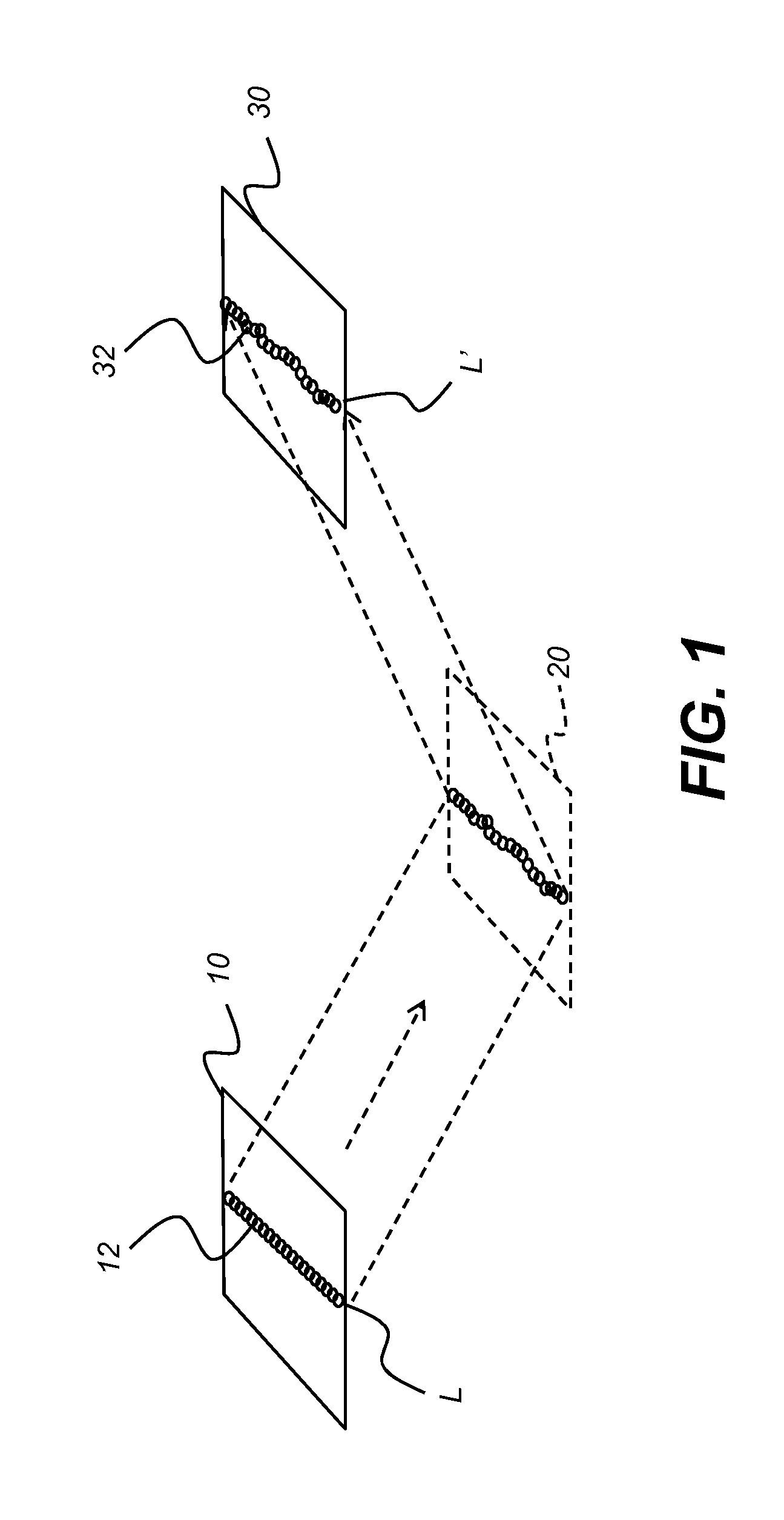
[0032]The schematic diagram of FIG. 1 shows, with the example of a single line of light L, how patterned light is used for obtaining surface contour information. A mapping is obtained as an illumination array 10 directs a pattern of light onto a surface 20 and a corresponding image of a line L′ is formed on an imaging sensor array 30. Each pixel 32 on imaging sensor array 32 maps to a corresponding pixel 12 on illumination array 10 according to modulation by surface 20. Shifts in pixel position, as represented in FIG. 1, yield...


PUM


Abstract

A method for mapping a sensor pixel array to an illumination pixel array according to a surface forms a group map by assigning each pixel on the sensor array to a corresponding group of an ordered set of groups, each group defined by a set of p adjacent pixels on the illumination pixel array by projecting and recording at least n projected images from a first set of n binary patterns, with transitions between pixels in each of the n binary patterns only at group boundaries. At least m images from a second set of m binary patterns are projected and recorded, with one or more transitions between pixels in each of the m binary pattern offset from group boundaries. At least p multiline images are projected and recorded. Lines in the recorded multiline images are correlated with lines in the multiline images according to the group map.

Description

FIELD OF THE INVENTION[0001]The disclosure relates generally to the field of surface shape imaging and more particularly relates to intraoral surface imaging and measurement.BACKGROUND OF THE INVENTION[0002]Techniques have been developed for obtaining surface contour information from various types of objects in medical, industrial, and other applications. Optical 3-dimensional (3-D) measurement methods provide shape and depth information using images obtained from patterns of light directed onto a surface. Various types of imaging methods generate a series of light patterns and use focus or triangulation to detect changes in surface shape over the illuminated area.[0003]Fringe projection imaging uses patterned or structured light and triangulation to obtain surface contour information for structures of various types. In fringe projection imaging, a pattern of lines of an interference fringe or grating is projected toward the surface of an object from a given angle. The projected pat...

Claims


Application Information

Patent Timeline
Patent Type & Authority Applications(United States)
IPC IPC(8): H04N13/02
CPCA61C9/006G06T2207/30036G06T7/0057G01B11/2513G06T7/521
Inventor MILCH, JAMES R.
Owner DENTAL IMAGING TECH
Why Eureka
Try Eureka