

Polarizer, polarizer producing process, projector, liquid crystal device, and electronic device
a technology of polarizers and polarising elements, applied in the field of polarizers, can solve the problems of poor oxidation resistance, film is not suited for actual use, and low attenuation coefficients
- Summary
- Abstract
- Description
- Claims
- Application Information
AI Technical Summary
Benefits of technology
Problems solved by technology
Method used
Image

Examples
first embodiment
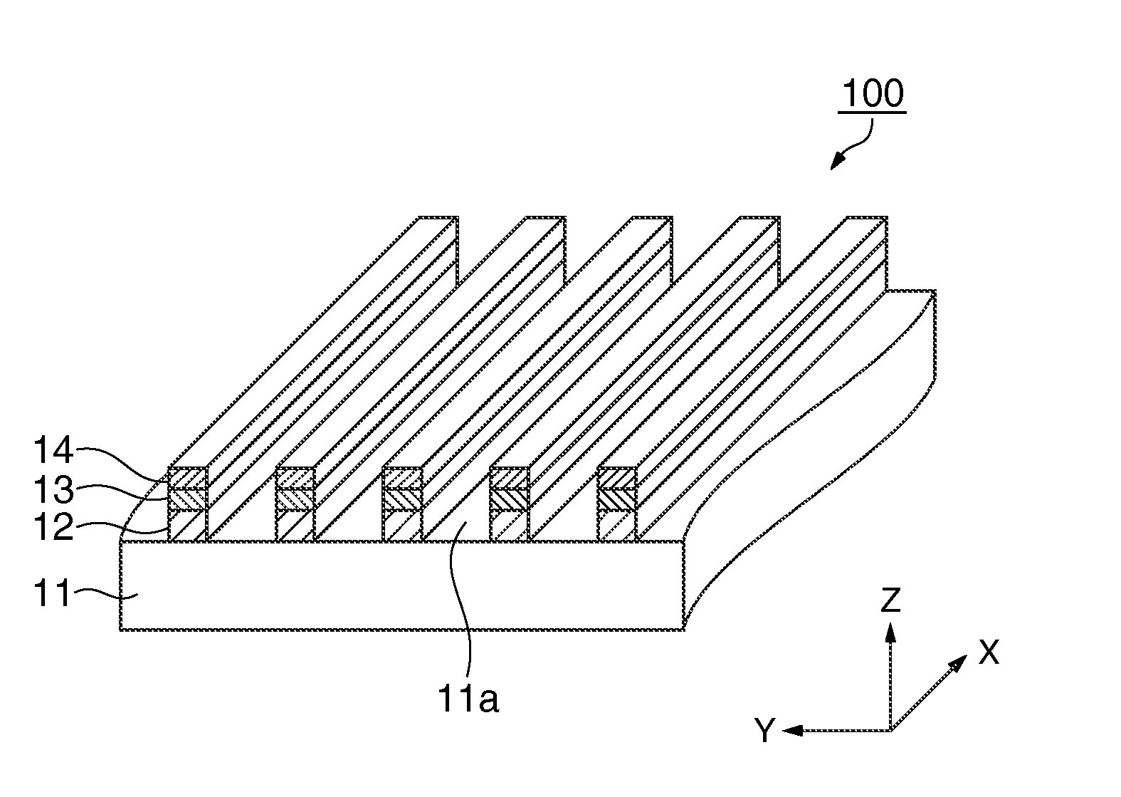
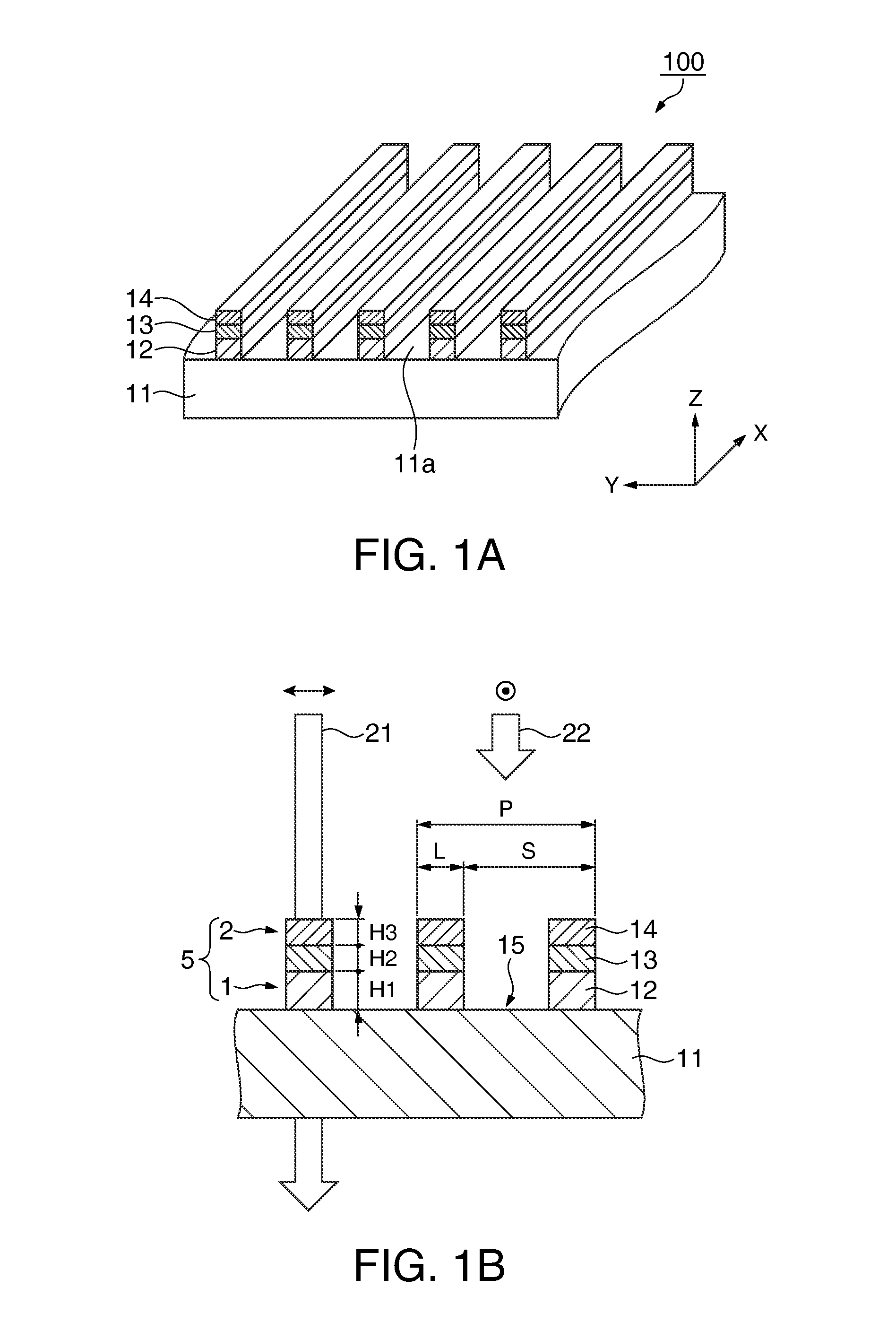
[0033]A polarizer and a polarizer producing process according to an embodiment of the invention are described below with reference to the accompanying drawings. FIGS. 1A and 1B are schematic diagrams of a polarizer 100 of the present embodiment. FIG. 1A is a partial perspective view, and FIG. 1B is a partial cross sectional view of the polarizer 100 at the YZ plane.
[0034]In the following, the positional relationships between different members will be described with reference to an XYZ Cartesian coordinate system set herein for the purpose of explanation. The plane parallel to a surface 11a of a substrate 11 is defined as an XY plane, and the extension direction of stripe-shaped metal layers 12 of a first grating is defined as an X-axis direction. The direction along which the plurality of metal layers 12 is aligned (aligned direction) is a Y-axis direction. In the all drawings, the proportions of the thicknesses and the dimensions of the constituting members are appropriately varied...
example 1
[0070]A thin film of chromium nitride having a thickness of 35.0 nm was formed on a glass substrate by reactive sputtering to fabricate sample 2. The refractive index n and attenuation coefficient k of sample 2 were measured before and after heating at 300° C. for 150 hours in the atmosphere. The ellipsometric method (J. A. Woollam; M-2000) was used for the measurements of refractive index n and attenuation coefficient k. The measurement wavelength was 532 nm. The results are presented in Table 1.
example 2
[0071]A thin film of tantalum nitride having a thickness of 48.0 nm was formed on a glass substrate by reactive sputtering to fabricate sample 4. The refractive index n and attenuation coefficient k of sample 4 were measured before and after heating at 300° C. for 150 hours in the atmosphere. The measurement results are presented in Table 1.
PUM
| Property | Measurement | Unit |
|---|---|---|
| height H2 | aaaaa | aaaaa |
| height H2 | aaaaa | aaaaa |
| height H3 | aaaaa | aaaaa |
Abstract
Description
Claims
Application Information