Systems and methods for assessment of oxygenation

a technology of oxygenation and oxygenation, applied in the field of systems and methods for oxygenation assessment, can solve the problems of significant radiation loss of lgrs, and achieve the effects of reducing penetration depth, improving snr, and optimizing measurements

Inactive Publication Date: 2013-05-23
O2 INSIGHTS
View PDF1 Cites 7 Cited by
  • Summary
  • Abstract
  • Description
  • Claims
  • Application Information

AI Technical Summary

Benefits of technology

[0009]In a first aspect of the present invention, a scanner for assessing localized oxygenation of a desired region of interest comprises a handheld housing having a proximal end and a distal end. The scanner is configured to use electron paramagnetic resonance to assess localized oxygenation in the desired region of interest. A radiofrequency (RF) bridge (further explained in the detailed description) assembly having a surface resonator coil is disposed within the housing and also disposed adjacent the distal end of the. The RF bridge assembly is configured to both generate RF excitation signals and read electron paramagnetic resonance signals. The RF bridge comprises at least one of the following: an oscillator, an attenuator, a circulator, a resonator, a detector, a reference arm, a pre-amplifier, an automatic frequency controller, a SAW oscillator, or a tuning display. The following description of these elements is taken from “Theory, Instrumentation, and Applications of Electron Paramagnetic Resonance Oximetry” by Rizwan Ahmad and Periannan Kuppusamy, published Mar. 10, 2010 in Chem. Rev. 2010, 110, pages 3212-3236, the entire contents incorporated herein by reference. The EPR resonator design is important to maximize sensitivity and must be tailored to accommodate the sample with the highest possible filling factor x quality factor product. The quality factor, Q, is the ratio of energy stored to energy lost by the resonator, while the filling factor is the fraction of total RF magnetic field power entering the resonator that is incident upon the sample. A higher Q allows larger detectable changes during absorption and hence improves signal intensity. The resonator must be a mechanically stable structure and should make most efficient use of the space within the magnet. Space constraints present a major consideration in the choice of the resonator design for EPR imaging. Automatic coupling adjustment and frequency tuning can be used to suppress motion-induced distortion that occurs in biological samples. In recent years, much effort has been focused on the development of lumped-parameter RF sample cavities for L- and S-bands. Typical embodiments may utilize but are not limited to two major types of such resonators, namely, loop-gap and reentrant, have been introduced and extensively discussed in the field. Loop-gap resonators (LGRs) provide a straightforward design and high filling factors as compared to standard distributed parameter RF cavities. However, because of the open structure of the inductive loop element, LGRs have significant radiation losses unless a shield is provided. The need for the shield leads to problems in achieving an optimum magnitude of modulation field and at least a 20% increase of overall resonator dimensions The reentrant resonator (RER) design forms a closed volume, it does not require any additional shield, thus providing substantial space savings as compared to LGRs. A number of RERs constructed of ceramic silverplated material are also reported,' offering improved rigidity and stability.
[0011]Additional preferred embodiments are similar to above described embodiments and may additionally provide modulation coils to modulate the substantially uniform magnetic field. As described in the above encorporated reference “Theory, Instrumentation, and Applications of Electron Paramagnetic Resonance Oximetry”: it is a common practice in CW EPR, to improve sensitivity, to modulate the magnetic field by adding an oscillating magnetic field using a pair of modulation coils and to detect the signal using a phase-locked loop detector, which is also called a phase-sensitive or a lock-in detector. The lock-in detector compares the EPR signal from the crystal with the reference signal, which comes from the same oscillator that generates the magnetic field. The lock-in detector only accepts the EPR signal that is phase coherent to the reference signal. The advantages of lock-in detection include less than 1 / f noise from the detection diode and elimination of the baseline instabilities due to drift DC electronics. Additionally to improve the substantially uniform magnetic field the handheld scanner may further comprise a Hall Effect sensor for use in field generation feedback.
[0014]Additionally, typical embodiments of the invention as described above and their methods of use may employ tuning the handheld scanner to optimize measurements. Tunable parameters include but are not limited to: i) Radiation frequency: An increase in the radiation frequency improves the SNR but at the same time results in unwanted nonresonant absorption and reduction in penetration depth. (ii) Magnetic gradient: An increase in magnetic gradient strength thermally burdens the gradient coils and degrades SNR but improves spatial resolution. (iii) RF power: An increase in RF power improves SNR but may also result in heating of the sample and power saturation-induced line broadening. (iv) Quality factor: A high Q of a resonator, along with critical coupling, improves SNR but also leads to extra sensitivity to sample motion. (v) Modulation amplitude: An increase in modulation amplitude improves SNR but exerts extra burden on the modulation coils and also results in line shape distortion, which is generally corrected by postprocessing. (vi) Sweep time: Increasing the magnetic field sweep time for each spectral scan improves SNR but prolongs the acquisition time, which can be very critical for in vivo applications. (vii) Number of projections: For imaging, collecting data along a large number of orientations generally improves reconstruction quality but only at the cost of increased acquisition time. The above description of tuning is taken from the encorporated reference “Theory, Instrumentation, and Applications of Electron Paramagnetic Resonance Oximetry.”

Problems solved by technology

However, because of the open structure of the inductive loop element, LGRs have significant radiation losses unless a shield is provided.

Method used


Image

  • Systems and methods for assessment of oxygenation
  • Systems and methods for assessment of oxygenation
  • Systems and methods for assessment of oxygenation

Examples


Embodiment Construction

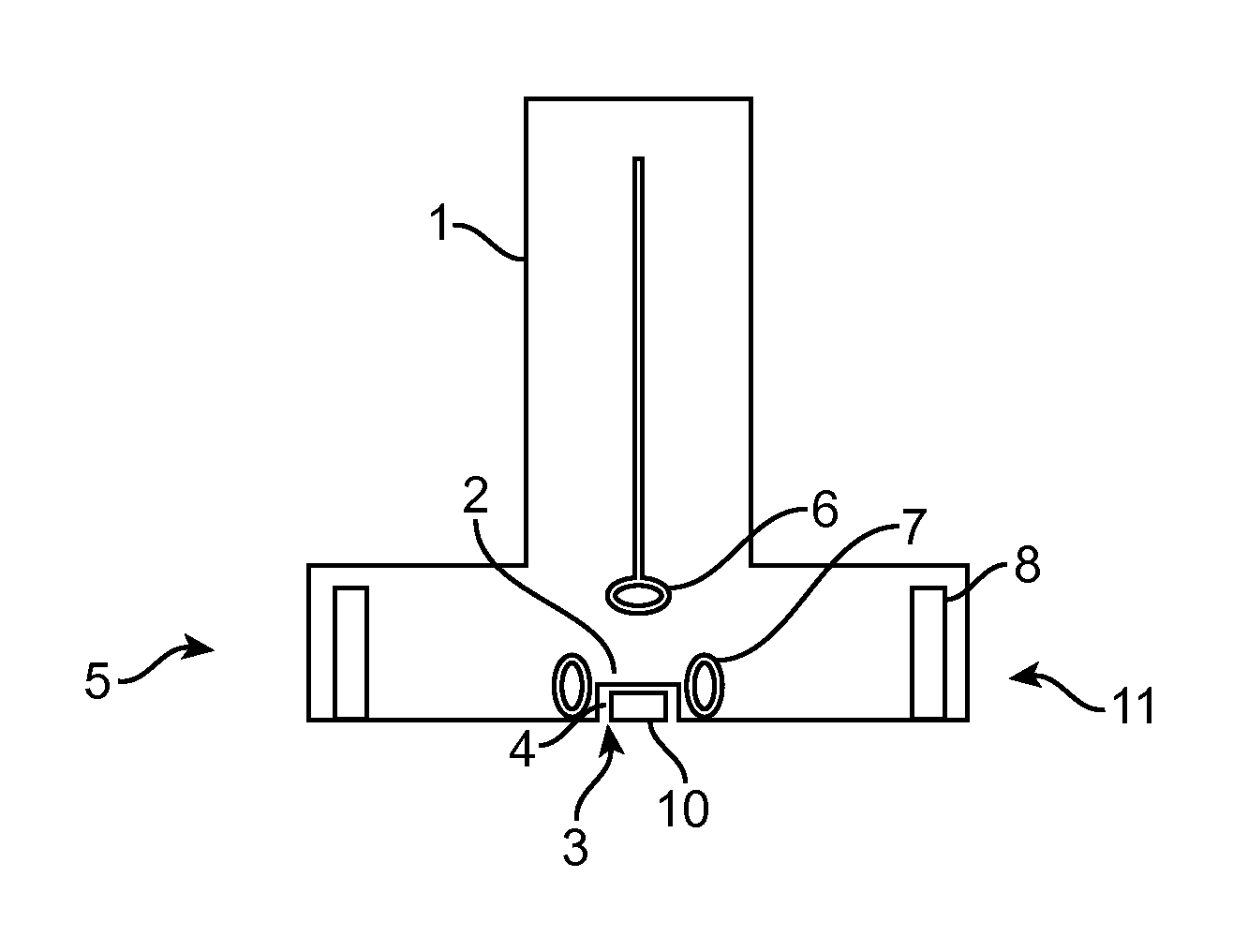
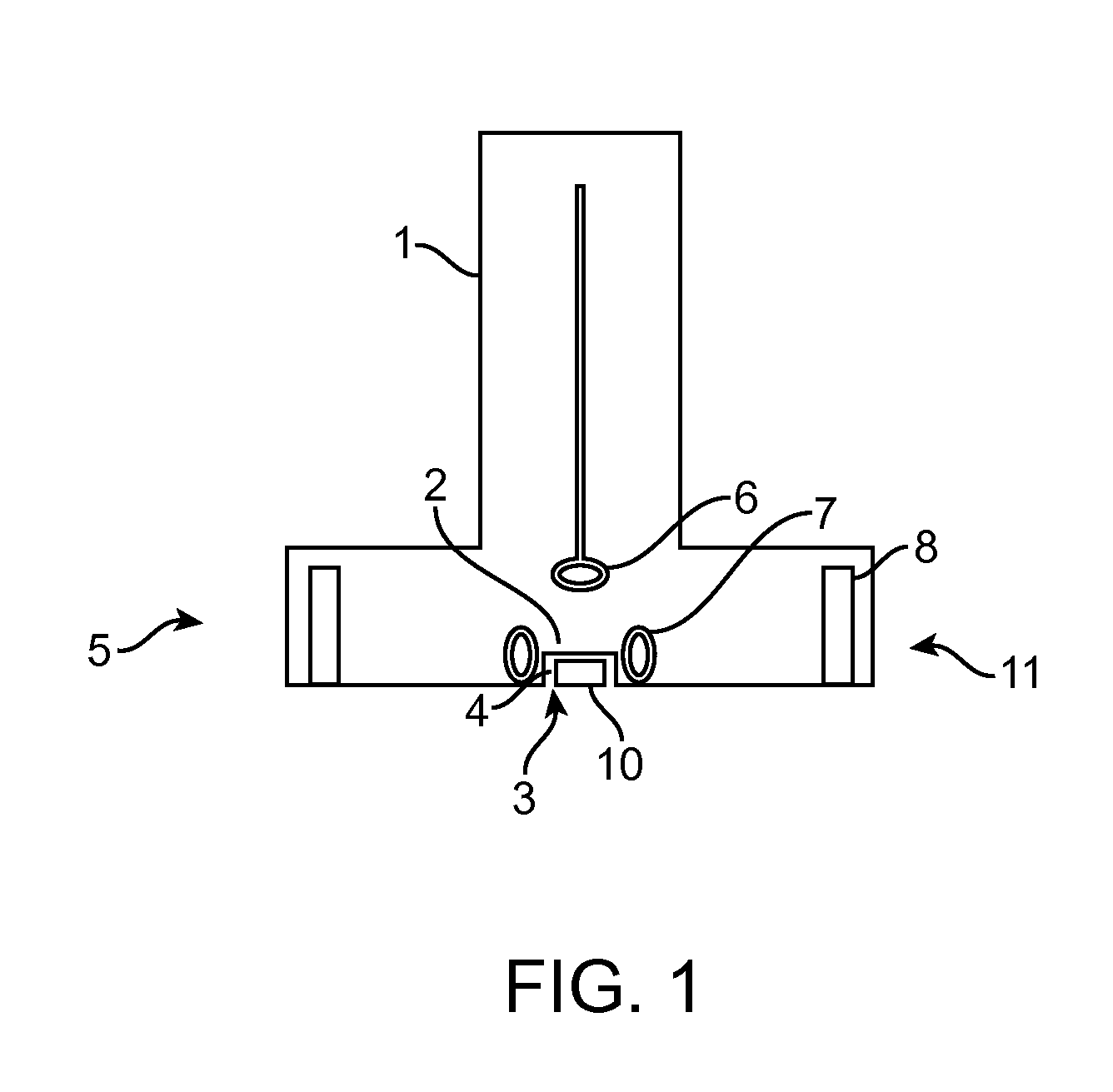
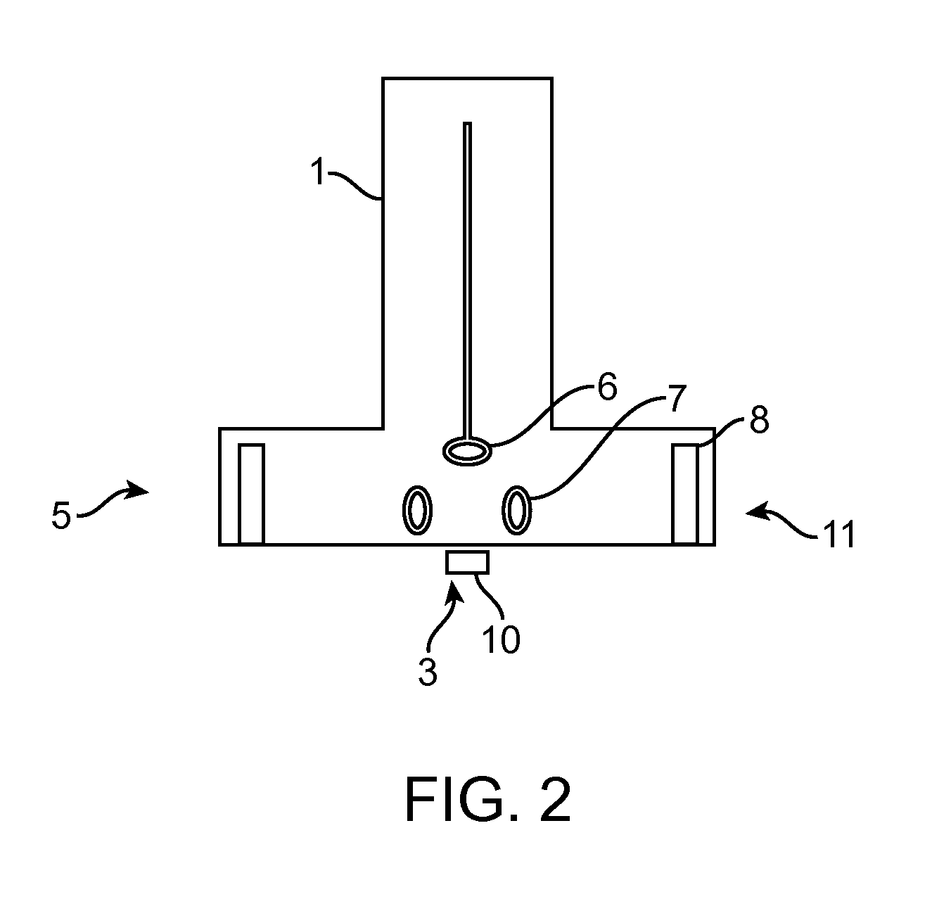
[0025]Disclosed herein are exemplary embodiments of a novel system and methods for measuring oxygen tension noninvasively or minimally invasively in either a human or animal subject. Oxygen tension measurement with the systems and methods described below are based upon the principle of electron paramagnetic resonance (EPR) oximetry. In the novel methods, any suitable paramagnetic probe for EPR oximetry such as india ink, coals, char, carbon black, lithium phthalocyanine, lithium naphthalocyanine, nitroxides, or trityl radicals is applied to a localized site on a subject and an EPR reader device consisting of a handheld scanner is used to excite and read the EPR probe material at the site of interest either under normobaric or hyperbaric pressure. The novel handheld scanner will apply a uniform magnetic field at the site of interest, excite the paramagnetic probes with a radiofrequency wave, measure the EPR signal, analyze the detected signal, and display the oxygen tension measured ...


PUM


Abstract

A scanner for assessing localized oxygenation of a desired region of interest includes a handheld housing having a proximal end and a distal end. A resonator coil is disposed within the housing and also disposed adjacent the distal end of the housing. The resonator coil is configured to both excite and read paramagnetic materials. A magnet is disposed within the housing and also disposed adjacent the distal end of the housing. The magnet is configured to provide a substantially uniform magnetic field over the desired region of interest. The scanner is configured to use electron paramagnetic resonance to assess localized oxygenation in the desired region.

Description

CROSS-REFERENCE TO RELATED APPLICATIONS[0001]The present application claims priority from provisional patent application No. 61 / 490,944 (Attorney Docket No. 40279-703.101), filed on May 27, 2011, the entire contents of which are incorporated herein by reference. The present application is related to the following co-pending patent applications: US Patent Publication Nos. 2010 / 0172843; 2005 / 0203292; and U.S. Provisional Patent Application No. 61 / 486,519; the entire content of each is incorporated herein by reference. The present application is also related to U.S. Pat. No. 7,662,362; the entire contents of which are incorporated herein by reference.BACKGROUND OF THE INVENTION[0002]The present invention generally relates to systems and methods for assessment of oxygenation. More particularly, the present invention relates to systems and methods for measuring oxygen tensions in biological systems such as wounds or organs in humans or animals, or in other regions of the body. Measuremen...

Claims


Application Information

Patent Timeline
Patent Type & Authority Applications(United States)
IPC IPC(8): G01R33/60G01R33/38
CPCG01R33/60A61B5/14542A61B5/055G01R33/38
Inventor KUPPUSAMY, PERIANNANGUPTA, SAMIT KUMARRUSHENBERG, ROBERT LAWRENCE
Owner O2 INSIGHTS
Why Eureka
Try Eureka