Tissue transfer systems

a tissue transfer and tissue technology, applied in the field of medical devices, can solve the problems of difficult detection, difficult use and adoption, and difficult identification of desirable locations for injecting fat (located between the pectoral muscles and breast ducts), and achieve the effects of minimizing or inhibiting any clogging of fat, accurate control, and minimizing obstruction

Active Publication Date: 2013-05-23
LIFECELL
View PDF3 Cites 32 Cited by
  • Summary
  • Abstract
  • Description
  • Claims
  • Application Information

AI Technical Summary

Benefits of technology

[0013]In addition to the detection of tissue types for facilitating the accurate injection of the fat, various instruments may be utilized within or in conjunction with the cannula for delivering precise volumes of the fat in a controlled manner. One example is a screw-type injection mechanism having a fluted shaft. The screw mechanism may be rotatably positioned within the cannula and it may have a distal opening for injecting the fat delivered through the cannula. As the screw mechanism rotates, any fat contained within a connected reservoir or within the cannula itself may be meted out through the distal opening. Starting or stopping the injection of the fat may be accurately controlled by starting or stopping rotation of the mechanism. An optional retractable cover located along the distal end of the cannula may be used as well.
[0014]An entry port may be positioned along the handle in proximity to the proximal end of screw mechanism such that fat for injection introduced into the handle may be taken up by the mechanism. The entry port may open into a chamber which is in fluid communication with the cannula and screw mechanism to minimize any clogging or obstruction which may occur due to the fat. Additionally and / or optionally, bristle stop members may be incorporated within the cannula lumen to further minimize or inhibit any clogging of the fat during injection into the patient.
[0015]In yet another variation, the injection assembly may optionally incorporate an impeller-stator assembly within the housing of the handle to help accelerate the fat to a speed sufficient for injection as well as to uniformly dispense the fat through the cannula for uniform injection into the breast. In use, as the impeller rotates via a drive shaft, the fat contained within the housing or reservoir may be propelled distally through the assembly past the blades of the stator which remains static. As the fat is urged through the assembly, the flow may be uniform as it is urged through the cannula for injection into the breast tissue.

Problems solved by technology

However, this technique is subject to variability in physician technique potentially resulting in inconsistent results and is also subject to improper placement of the adipose tissue into undesirable regions within the breast.
The regions within the breast which are ideally avoided by the physician, such as the muscles or ducts of the breast, may be difficult to discern while the desirable locations for injecting the fat (located between the pectoral muscles and breast ducts) are also difficult to detect.
Prior attempts to accurately position the cannula for injection into the ideal locations within the breasts have been made but they have faced difficulties in use and adoption.

Method used


Image

  • Tissue transfer systems
  • Tissue transfer systems
  • Tissue transfer systems

Examples


Embodiment Construction

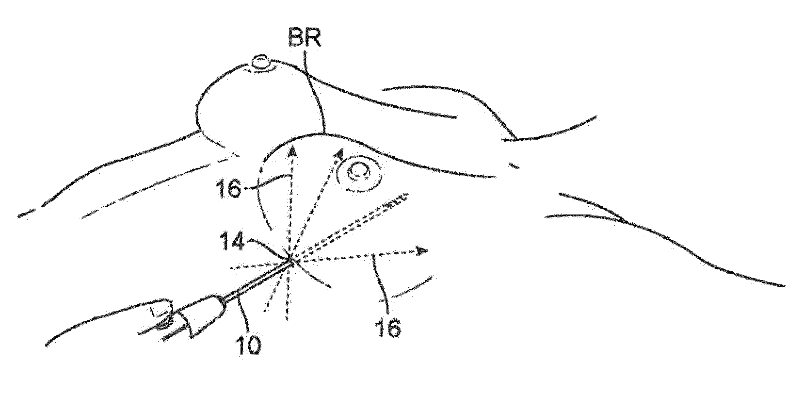
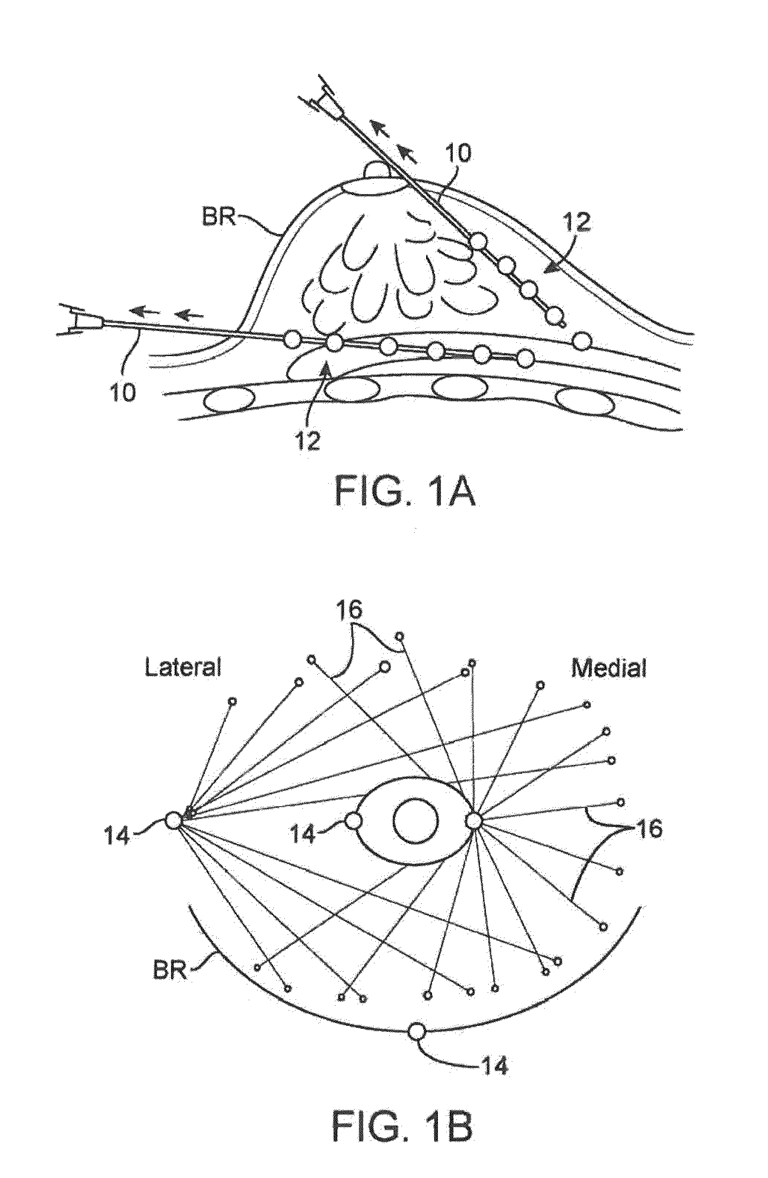
[0104]As shown in the cross-sectional side view and anterior view of FIGS. 1A and 1B, a cannula 10 may be inserted into the breast BR of a subject at one of several points of entry 14 in proximity to the nipple and circumference of the breast BR. After insertion of the cannula 10 into the breast, the cannula 10 may be withdrawn from the breast BR while injecting the fat in multiple deposits of adipose tissue or fat 12 such that the deposited fat 12 remains within the tract 16 formed by the withdrawn cannula 10. Multiple tracts 16 of the deposited fat 12 may be injected within the breast utilizing the common entry points 14 until the breast has been desirably remodeled and / or augmented.

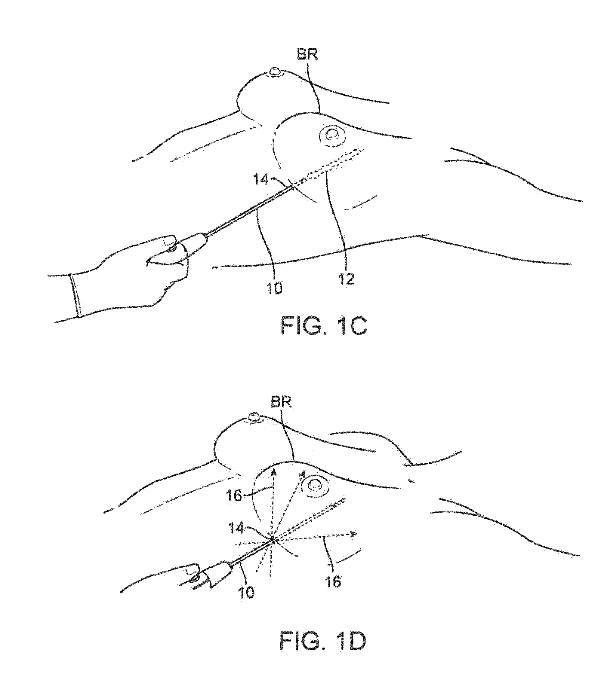
[0105]FIGS. 1C and 1D illustrate an example of how the cannula 10 may be inserted into a single entry point 14 beneath the breast BR and how the fat 12 may be deposited along a tract defined by the cannula 10. With the cannula 10 positioned through the entry point 14 within the breast BR, the cannula 1...


PUM


Abstract

Devices and methods for tissue transfer are described where a cannula may be inserted into the breast of a subject at one of several points of entry. Insertion of the cannula into the breast may be accomplished by using a guidance system to distinguish between tissue types. Once desirably positioned, the cannula may be withdrawn from the breast while automatically (or manually) injecting the fat in multiple deposits of adipose tissue or fat such that the deposited fat remains within the tract formed by the withdrawn cannula. Multiple tracts of the deposited fat may be injected within the breast until the breast has been desirably remodeled and/or augmented.

Description

CROSS-REFERENCE TO RELATED APPLICATIONS[0001]This application is a continuation of U.S. patent application Ser. No. 13 / 664,925 filed Oct. 31, 2012, which is a continuation-in-part of U.S. patent application Ser. No. 13 / 371,270 filed Feb. 10, 2012 which claims the benefit of priority to U.S. Prov. App. Nos. 61 / 442,060 filed Feb. 11, 2011; 61 / 489,811 filed May 25, 2011; and 61 / 510,967 filed Jul. 22, 2011, each of which is incorporated herein by reference in its entirety.FIELD OF THE INVENTION[0002]The present invention relates generally to medical devices and methods used for transferring tissue into a region of the body. More particularly, the present invention relates to apparatus and methods for transferring fat tissue into a region of the body, such as a breast, in a selectively controlled manner.BACKGROUND OF THE INVENTION[0003]Lipomodeling is a procedure which is typically performed under general anesthesia. Adipose tissue or fat is usually harvested from one part of the body su...

Claims


Application Information

Patent Timeline
Patent Type & Authority Applications(United States)
IPC IPC(8): A61M5/145
CPCA61M5/1452A61M2005/16863A61L2430/34A61L2400/06A61L2430/04A61L27/3604A61M5/3287A61M2202/08A61B90/13A61B2034/2055A61B2090/306
Inventor RIMSA, JOSEPHDOMECUS, BRIAN J.JONES, CHRISTOPHER S.LINGANE, PAUL JAMES
Owner LIFECELL
Why Eureka
Try Eureka