
Implant

a technology of implants and splints, applied in the field of implants, can solve the problems of the human body, affecting the performance of artificial joints, and separating from artificial joints, etc., and achieves the effects of high initial strength, and high initial bending strength

Inactive Publication Date: 2013-05-23
U & I INC
View PDF5 Cites 10 Cited by
  • Summary
  • Abstract
  • Description
  • Claims
  • Application Information

AI Technical Summary

Benefits of technology

The present invention aims to provide several types of implants with specific properties. These include: i) an implant that has high strength and is similar to bone; ii) an implant that is strongest in bending and pullout until an artificial joint is fixed on bone; iii) an implant that has a controlled decomposition rate to maintain strength until it is fixed in bone, without causing any harmful inflammation; iv) an implant that is safe and has no side effects from its own decomposed products; v) an implant that allows bone cells to grow and replace the implant with bone; and vi) an implant that is securely fixed around bone.

Problems solved by technology

The bone cement can be broken after an operation, and the eluted substances and particles of the bone cement can have a harmful effect on the performance of an artificial joint and the human body.
In particular, it has been reported that the particles of the bone cement block pulmonary blood vessels to cause death.
However, there is a problem in that HA separates from an artificial joint.
Meanwhile, a screw, which is made of only a biodegradable polymer, has been used as a fixing implant for improving the bone union of an artificial joint, but is problematic in that it has insufficient mechanical strength and is uniformly decomposed.

Method used


Image

  • Implant
  • Implant
  • Implant

Examples


preparation examples

[0085]The components having composition ratios given in Table 1 below were charged into a crucible made of stainless steel (SUS 410) and having an inner diameter of 50 mm.

[0086]Subsequently, The crucible was heated to a temperature of 700° C.˜750° C. using a resistance heating furnace while argon gas flowing around the crucible such that iron, nickel, manganese, aluminum and magnesium charged in the crucible did not come into contact with air, so as to melt iron, nickel, aluminum, manganese and magnesium. The molten iron, nickel, aluminum, manganese and magnesium were stirred by shaking the crucible such that they were easily mixed with each other. The completely-molten magnesium alloy was cooled to prepare a solid magnesium alloy. In this case, in order to improve the mechanical strength of the solid magnesium alloy, the molten magnesium alloy was rapidly cooled by immersing the crucible into water (20° C.).

TABLE 1Fe (parts byNi (parts byAl (parts byMn (partsMg (partsCa (partsweigh...

example 1

[0087]The biodegradable magnesium alloy of Preparation Example 1 was pulverized to obtain powder having an average particle size of 500 μmu (hereinafter, referred to as “biodegradable magnesium alloy powder”).

[0088]The biodegradable magnesium alloy powder was mixed with a biodegradable polymer (LPLG (poly(L-lactide-co-glycolide))) at a volume ratio of 85:15. Thereafter, the mixture was pressed at a temperature of 200° C. and a pressure of 5 atms to manufacture a screw-shaped implant.

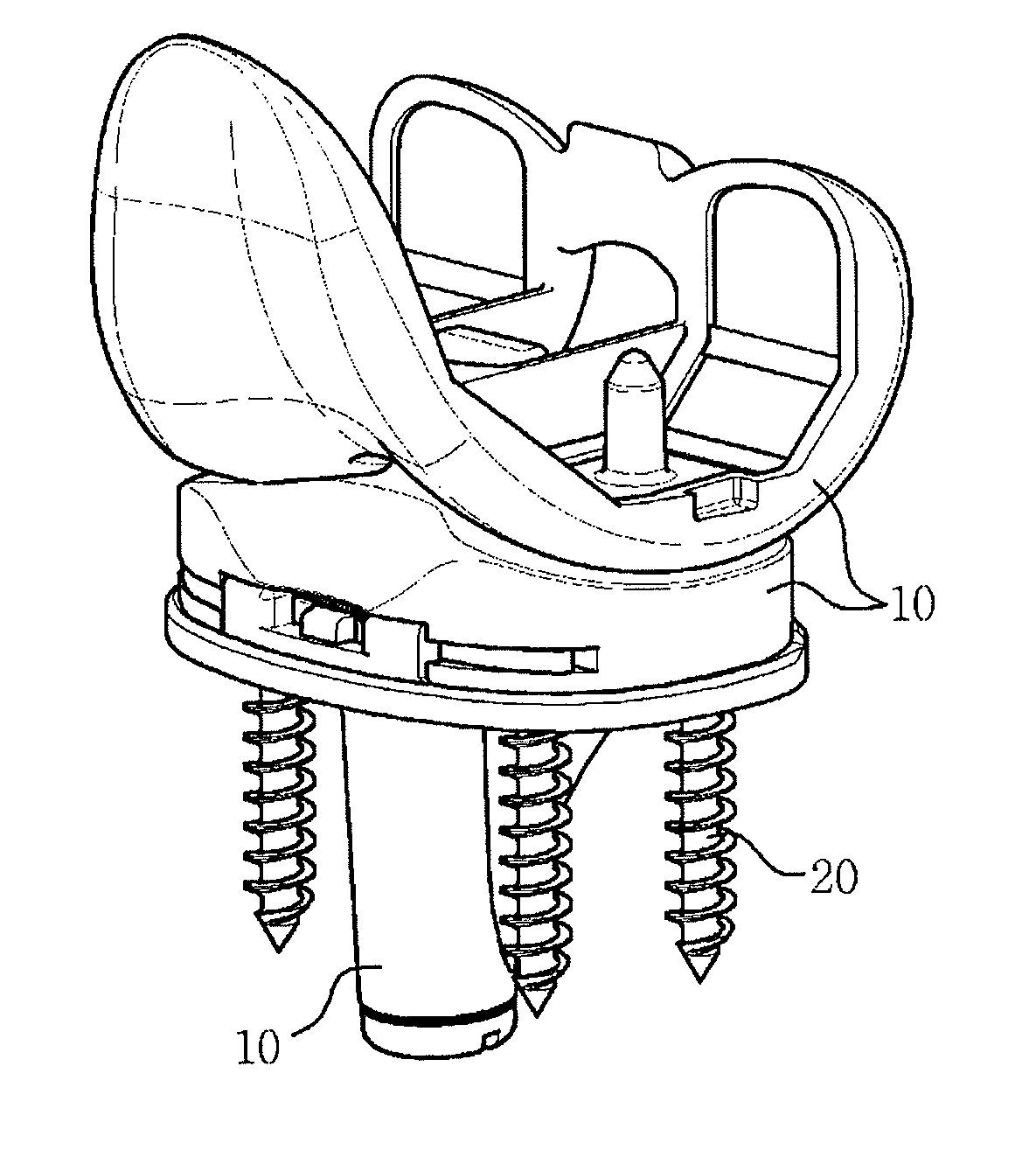
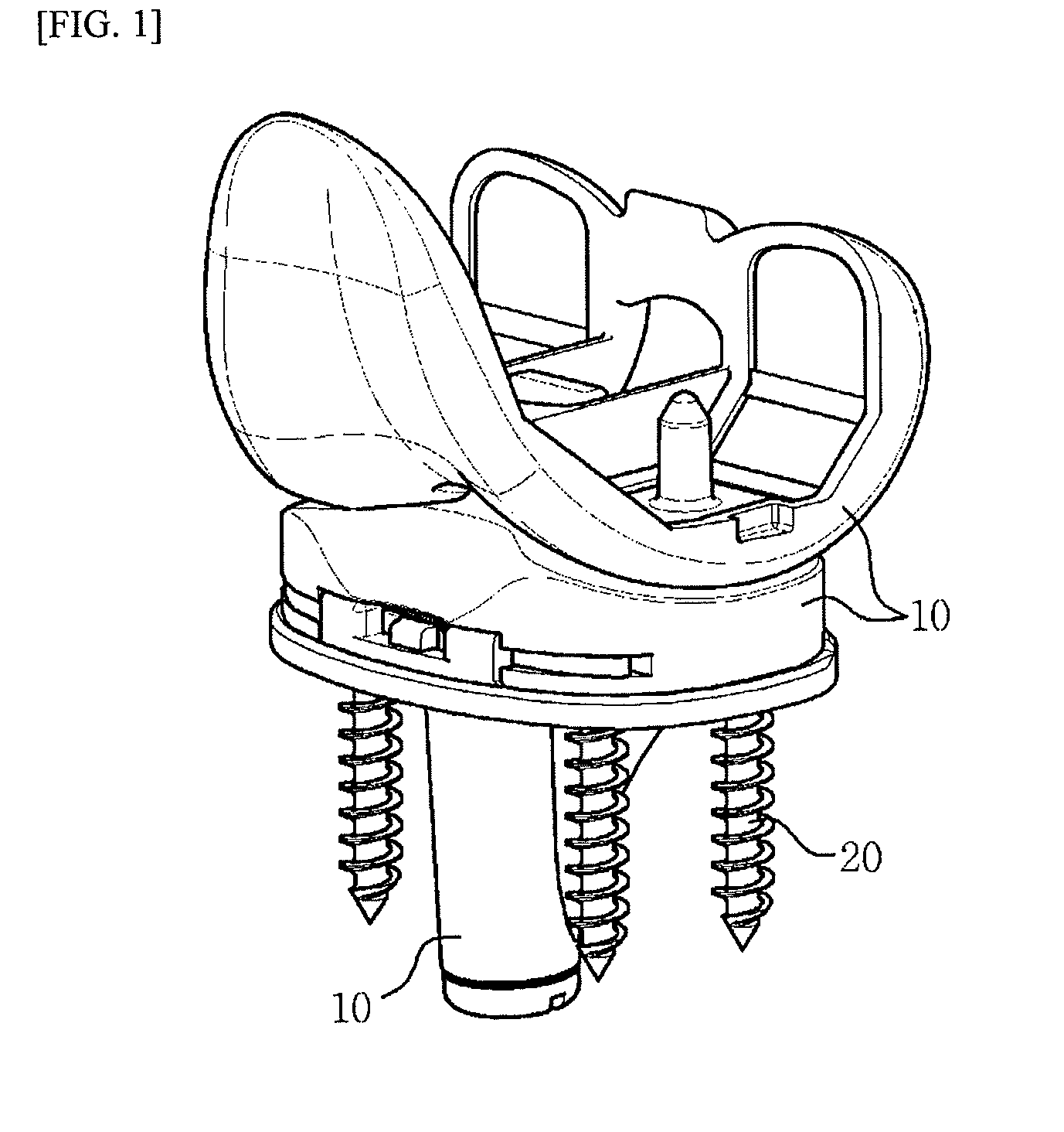
[0089]FIG. 2 is a photograph showing an artificial joint mounted with the implant manufactured in Example 1.

[0090]Referring to FIG. 2, the implant (arrow) mounted in the artificial joint (brand name: Optigen, manufactured by Yon & I Corp.) is accurately depicted.

example 2

[0091]The biodegradable magnesium alloy of Preparation Example 1 was extruded at an extrusion temperature of 400° C., and the reduction ratio (extrusion ratio) of the section area of the biodegradable magnesium alloy before and after extrusion was fixed at 15:1. The extruded magnesium alloy was processed to such a degree that it can be transplanted into a rat, so as to manufacture an implant.


PUM


Abstract

The present invention provides an implant, which is used to fix an artificial joint in bone, including a biodegradable magnesium alloy.

Description

CROSS REFERENCE TO RELATED APPLICATION[0001]This application claims the benefit of Korean Patent Application No. KR 10-2009-0120346, filed Dec. 7, 2009, which is hereby incorporated by reference in its entirety into this application.BACKGROUND OF THE INVENTION[0002]1. Technical Field[0003]The present invention relates to an implant.[0004]2. Description of the Related Art[0005]A function of artificial joints (for example, hip joint implants, knee joint implants, etc.) is to grow bone tissues when they are transplanted into a bone. In this case, bone tissues grow and thus the artificial joint is fixed in the bone. In conventional artificial joints, an artificial joint is coated with bone cement or hydroxyapatite (HA) in order to improve the interfacial force between the bone tissue and the artificial joint. Here, in the case of bone cement, the bone cement is kneaded and then adhered to an artificial joint at the time of the operation. The bone cement can be broken after an operation,...

Claims


Application Information

Patent Timeline
Patent Type & Authority Applications(United States)
IPC IPC(8): A61F2/30
CPCA61L27/047A61L27/58A61F2/30749A61L31/148A61L31/022A61F2/46A61F2002/30064A61F2002/4631A61L27/56
Inventor KOO, JA-KYOSEOK, HYUN-KWANGYANG, SEOK-JOKIM, YU-CHANKIM, JONG-TACK
Owner U & I INC
Learn More