Vehicular transmission with power take-off unit

a technology of power take-off unit and transmission shaft, which is applied in the direction of mechanical equipment, transportation and packaging, and manufacturing, etc., to achieve the effects of simple manufacturing, large resistance torque, and easy assembly

Inactive Publication Date: 2013-05-30
ZF FRIEDRICHSHAFEN AG
View PDF7 Cites 6 Cited by
  • Summary
  • Abstract
  • Description
  • Claims
  • Application Information

AI Technical Summary

Benefits of technology

[0011]In another preferred embodiment, the lay shaft is designed as a pinion shaft, meaning that the pinion is designed as single piece with the lay shaft. Thus, the manufacturing is simpler.
[0012]In another preferred embodiment, the lay shaft is connected via a connector, for instance a polygon or splined shaft profile, with the auxiliary drive shaft. This means that both shafts can be easily assembled in the axial direction, whereby a pre-assembly of the bearing device with a pinion shaft and bearings is possible. Furthermore, a simple exchange of the auxiliary drive becomes possible.
[0013]In an additional preferred embodiment, the bearing device has a hollow cylindrical section on a longitudinal axis, wherein the two bearing boreholes are coaxially positioned along the longitudinal axis and the hollow cylindrical section has a window, i.e., has a recess in the area of the tooth engagement of the spur wheel section. The hollow cylindrical section creates a large resistance torque to accommodate the bearing forces, on the other hand, the window allows engagement between the pinion and the gear wheel at the transmission shaft.
[0014]In an additional preferred embodiment, the transmission is designed as double clutch transmission with two coaxially positioned drive shafts which can be driven, via the pinion gear stage, by the auxiliary drive. It creates the advantage that the double clutch transmissions which are used in today's motor vehicles can be adapted to a hybrid drive, meaning an electrical auxiliary drive, meaning that they can be “hybridized”.
[0015]In an additional aspect of the invention, a device for driving a transmission shaft is provided by an auxiliary drive, a lay shaft for driving a transmission shaft is mounted, via a double spur gear stage, in a bearing device. The advantage hereby is a compact and axially parallel bearing of the lay shaft in the bearing device, which is part of the auxiliary drive. The design of the bearing device matches with the above described bearing device.

Problems solved by technology

Attaching the electric machine to one of the transmission shafts causes problems when not enough construction space is available for a bearing of the drive shaft of the electric machine.

Method used


Image

  • Vehicular transmission with power take-off unit
  • Vehicular transmission with power take-off unit
  • Vehicular transmission with power take-off unit

Examples


Embodiment Construction

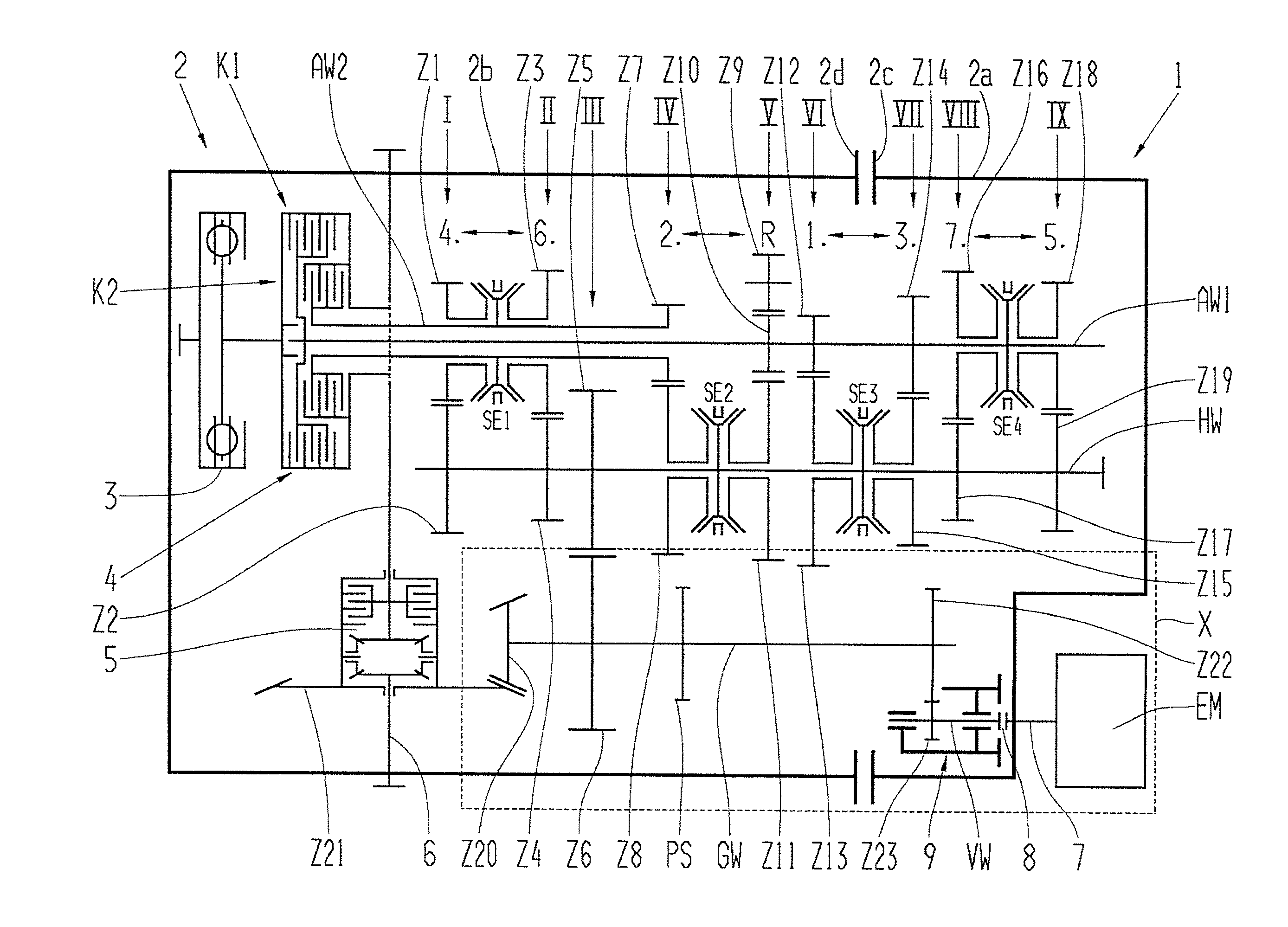
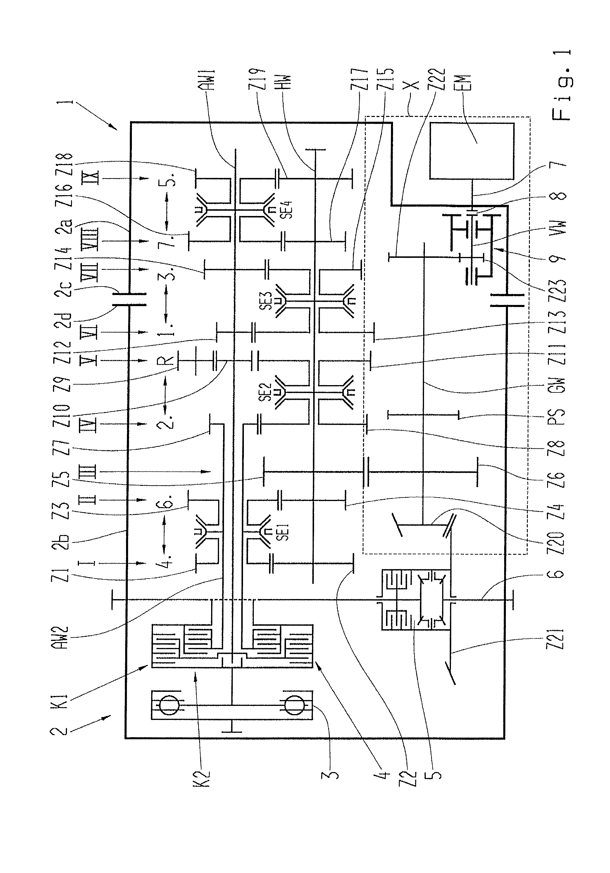
[0021]FIG. 1 shows a schematic presentation of a double clutch transmission 1 for a motor vehicle with an auxiliary drive, designed as an electric machine EM. The double clutch transmission 1 comprises a two-part transmission housing 2 with a rear housing part 2a and a front housing part 2b, which are connected with each other via a housing flange 2c, 2d. In the transmission housing 2, meaning in the front housing part 2b, at the drive side of a not shown combustion engine of the motor vehicle, a driven torsion vibration damper 3 as well as a double clutch 4 are positioned, comprising of a first outer clutch K1 and a second, inner clutch K2. The double clutch 4, which is driven on the motor side via the torsion vibration damper 3, drives on its own, via a first drive shaft AW1 which is driven by the first clutch K1, a first partial transmission TG1, and driven via a second clutch K2, a second drive shaft AW2, designed as a hollow shaft and positioned coaxial to the first drive shaft...


PUM


Abstract

A transmission, for a motor vehicle with an auxiliary drive (EM), having a first housing part (2a), a second housing part, a transmission shaft (GW), an auxiliary drive shaft which can be driven by the auxiliary drive (EM), a lay shaft (VW) that is positioned axially parallel to the transmission shaft (GW) and coaxial to the auxiliary drive shaft. The lay shaft (VW) is connected, via a spur wheel stage (Z22, Z23) with the transmission shaft (GW), and the lay shaft (VW) is connected in a rotationally fixed manner with the auxiliary drive shaft and is supported on both sides of the spur wheel stage (Z22, Z23) in a bearing device (9).

Description

[0001]This application claims priority from German patent application serial no. 10 2011 087 163.2 filed Nov. 28, 2011.FIELD OF THE INVENTION[0002]The invention concerns a transmission of a motor vehicle with an auxiliary drive, as well as a device to drive a transmission shaft by an auxiliary drive.BACKGROUND OF THE INVENTION[0003]It is known that today's motor vehicles, so-called hybrid vehicles, have beside the combustion engine as the drive machine an auxiliary drive in a form of an electric machine, whereby the auxiliary drive is attached to the transmission of the motor vehicle and drives the transmission. Attaching the electric machine to one of the transmission shafts causes problems when not enough construction space is available for a bearing of the drive shaft of the electric machine. Furthermore, the rotational speed of the electric machine needs to be reduced, meaning that an additional gear reduction stage is necessary.SUMMARY OF THE INVENTION[0004]It is the task of th...

Claims


Application Information

Patent Timeline
Patent Type & Authority Applications(United States)
IPC IPC(8): F16H3/02
CPCF16H3/02B60K6/405B60K6/48F16H3/006B60K2006/4808Y10T74/19233F16H2200/0017F16H2200/003F16H2200/0056Y02T10/6221Y02T10/626F16H3/089Y10T74/19014Y10T74/19056Y02T10/62
Inventor SCHNEIDER, THOMASFIRZLAFF, UWESCHMIDBERGER, FRANZHOHER, MARKUS
Owner ZF FRIEDRICHSHAFEN AG
Why Eureka
Try Eureka