Method of fabricating and apparatus of fabricating tunnel magnetic resistive element

a tunnel magnetic resistive element and fabrication method technology, applied in nanoinformatics, instruments, record information storage, etc., can solve the problems of remarkably reducing the throughput of production, affecting the yield factor at the time of device fabrication, and likely dispersion, so as to achieve low ra and high mr ratio

Inactive Publication Date: 2013-05-30
CANON ANELVA CORP
View PDF2 Cites 17 Cited by
  • Summary
  • Abstract
  • Description
  • Claims
  • Application Information

AI Technical Summary

Benefits of technology

[0029]According to the present invention, a method and an apparatus of fabricating a tunnel magnetic resistive element which does not show much dispersion in RA and capable of obtaining a high MR ratio in a low RA can be provided.

Problems solved by technology

However, the MgO formation method by the RF magnetron sputtering using the MgO sintering target gives rise to a problem that dispersion is likely to occur in normalized tunnel resistive value (RA) and there is a risk to remarkably deteriorate the yield factor at the time of device fabrication.
However, the method of repeating film formation and oxidation of metal Mg twice gives rise to a problem that shuttling between a film formation chamber and an oxidation processing chamber remarkably decreases throughput of production.
However, that case gives rise to a problem of increase of production costs for devices due to increase of the cost for apparatuses and increase of the area for installation and the like.
However, with the MR ratio in the low RA region being not more than 40%, performance of the tunnel magnetic resistive element with a MgO tunnel barrier layer is not sufficient.
In addition, due to unavailability of any example on dispersion of the RA that affects the yield factor significantly, it is uncertain whether or not the process is appropriate for production.

Method used


Image

  • Method of fabricating and apparatus of fabricating tunnel magnetic resistive element
  • Method of fabricating and apparatus of fabricating tunnel magnetic resistive element
  • Method of fabricating and apparatus of fabricating tunnel magnetic resistive element

Examples


example 1

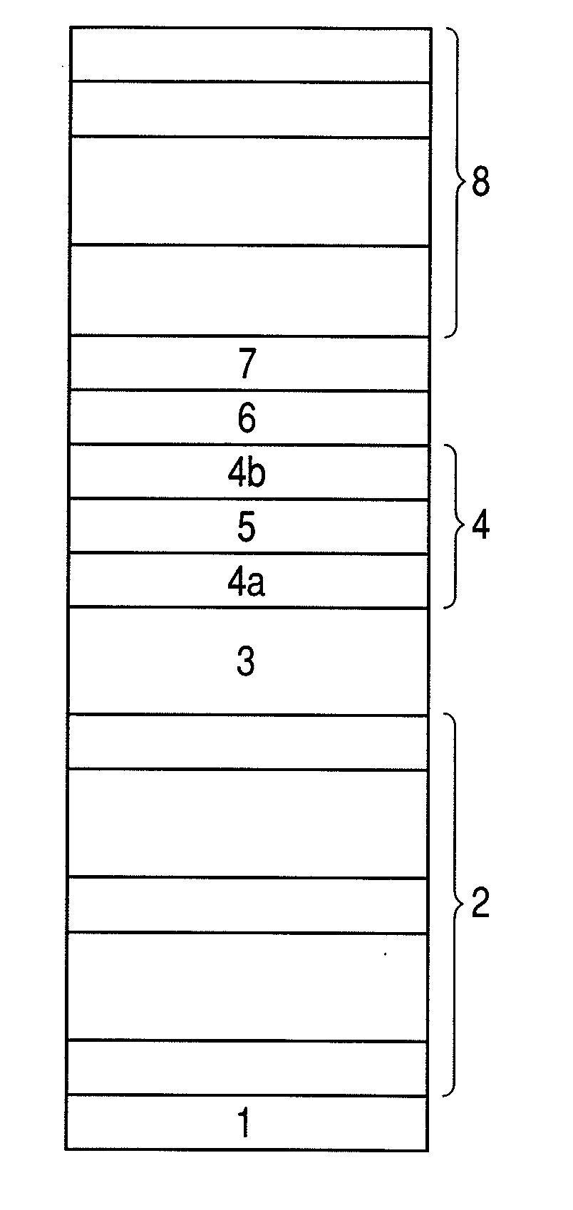
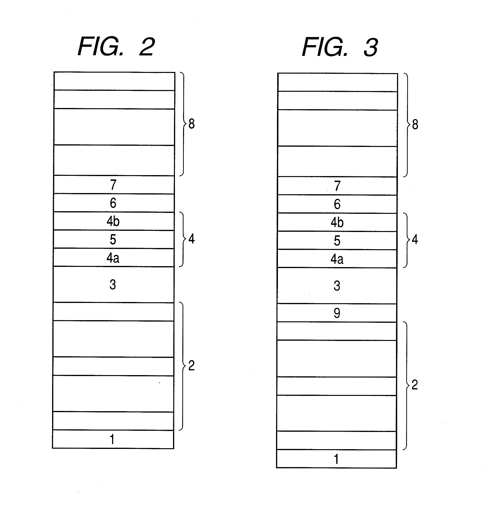
[0055]FIG. 3 is a film configuration diagram of a tunnel magnetic resistive element produced with a fabrication method and a fabrication apparatus related to the present invention. IrMn with thickness of 7 nm is used as antiferromagnetic layer 3. A Ru layer of 5 nm is used as its underlying layer 9. Otherwise, the film configuration is the same as that of FIG. 2.

[0056]With reference to FIG. 4, a forming method of a tunnel barrier layer related to the present example will be described. FIG. 4 is a flow chart of film formation of a tunnel barrier layer according to the present example. In a step S401, film formation was carried out until a first ferromagnetic layer is formed as described in the above embodiment. In a step S403, on a CoFeB layer to become the first ferromagnetic layer, film formation of metal Mg of 1.2 nm was carried out in the atmosphere obtained by independently introducing Ar gas at 15 sccm and oxygen at 5 sccm (the mixed oxygen concentration is 25%). Subsequently, ...

example 2

[0060]FIG. 6 illustrates a flow chart for forming a tunnel barrier layer in the case of stopping mixture of oxygen gas in the initial period and at the end of film formation at the occasion of oxygen doping at the time of film formation of the first metal layer. At that time, radical oxidation was used as a method of oxidizing the first metal layer. The film configuration in FIG. 2 was adopted for the film configuration of the tunnel magnetic resistive element.

[0061]With reference to FIG. 6, the flow of forming the tunnel barrier layer will be described below. In a step S601, film formation of up to the first ferromagnetic layer was carried out as described in the above embodiment. In a step S603, through the following three steps, film formation of the first metal layer was carried out on the first ferromagnetic layer. That is, at the initial stage of film formation of the first metal layer, film formation of the first metal layer was carried out in the Ar gas atmosphere without in...

example 3

[0068]FIG. 9 is a graph illustrating distribution of RA inside the substrate surface at the occasion of radical oxidation only with an oxidation time of 100 seconds in a tunnel magnetic resistive element with the same film configuration as the tunnel magnetic resistive element obtained through the same method of forming the MgO tunnel barrier as those used for Example 2. The abscissa axis is for distance from the center of the wafer having a diameter of 300 mm. For the purpose of comparison, the graph also shows RA distribution of a tunnel magnetic resistive element with an MgO tunnel barrier having been formed by RF sputtering directly from an MgO sintering target. According hereto, the RA distribution of the tunnel magnetic resistive element formed by the method of the present invention is 1.6% being a result apparently better than the RA distribution of 9.4% of the method by RF sputtering on the MgO sintering target.


PUM

PropertyMeasurementUnit
pressureaaaaaaaaaa
thicknessaaaaaaaaaa
thicknessaaaaaaaaaa

Abstract

One embodiment of the present invention is a method of fabricating a tunnel magnetic resistive element including a first ferromagnetic layer, a tunnel barrier layer and a second ferromagnetic layer, comprising a step of making the tunnel barrier layer, comprising the step of making the tunnel barrier layer includes the steps of: forming a first layer on the first ferromagnetic layer by applying DC power to a metal target and introducing sputtering gas without introducing oxygen gas in a sputtering chamber; and forming a second layer on the first layer by applying DC power to the metal target and introducing the sputtering gas and oxygen gas with the DC power to be applied to the metal target from the step of forming the first layer in the sputtering chamber, wherein the second layer is oxygen-doped.

Description

CROSS-REFERENCES TO RELATED APPLICATIONS[0001]This application is a continuation-in-part of U.S. patent application Ser. No. 12 / 190,864 filed on Aug. 13, 2008, which is a continuation of International Application No. PCT / JP2008 / 061554, filed Jun. 25, 2008.BACKGROUND OF THE INVENTION[0002]1. Field of the Invention[0003]The present invention relates to a magnetic reproducing head of a magnetic disk drive apparatus, a memory element of a magnetic random access memory and a magnetic sensor.[0004]2. Related Background Art[0005]A tunnel magnetic resistive element with crystalline MgO as a tunnel barrier layer obtains a huge MR ratio (percentage of magnetic resistive change) of 200% or more at the room temperature. Consequently, applications to a reproducing or read-out head of a magnetic disk drive apparatus, a memory element of magnetic random access memory (MRAM) and a magnetic sensor are being expected. In the case of a conventional tunnel magnetic resistive element obtained by adoptin...

Claims


Application Information

Patent Timeline
Patent Type & Authority Applications(United States)
IPC IPC(8): G11B5/39
CPCG11B5/3906G01R33/098B82Y25/00B82Y40/00C23C14/34C23C14/568C23C14/5853G11B5/3163G11B5/3909H01F41/18H01F41/307H01L43/08H01L43/12C23C14/081C23C14/3492G01R33/09B82Y10/00H10N50/10H10N50/01
Inventor TSUNEKAWA, KOJINAGAMINE, YOSHINORINISHIMURA, KAZUMASAERNULT, FRANCK
Owner CANON ANELVA CORP
Why Eureka
Try Eureka