
Image processing device and method, recording medium, and program

a technology of image processing and recording medium, applied in the field of image processing device and method, recording medium, and program, can solve the problems of insufficient amount and insufficient great visual stereoscopic effect (sense of depth) difficulty

Active Publication Date: 2013-05-30
SONY CORP
View PDF4 Cites 91 Cited by
  • Summary
  • Abstract
  • Description
  • Claims
  • Application Information

AI Technical Summary

Benefits of technology

The present invention relates to an image processing device, which can control the stereoscopic effect of a multi-viewpoint image. The device has several components including a viewpoint separating unit, a storage unit, a readout unit, a super-resolution processing unit, a noise reduction processing unit, and a parallax control unit. The device can store and read the separated single-viewpoint image data one viewpoint at a time. The super-resolution processing unit raises the resolution of the image data, and the noise reduction processing unit reduces the noise of the image data. The parallax control unit controls the amount of parallax between the single-viewpoint image data stored in the second storage unit. The device can also perform stereoscopic processing on the multi-viewpoint image by adjusting the parallax between the different viewpoints.

Problems solved by technology

Accordingly, with multi-viewpoint images obtained using such an imaging apparatus, restriction in size of the imaging lens and suppression in deterioration of resolution has led to insufficient amount of parallax, so sufficiently great visual stereoscopic effect (sense of depth) has been difficult.

Method used


Image

  • Image processing device and method, recording medium, and program
  • Image processing device and method, recording medium, and program
  • Image processing device and method, recording medium, and program

Examples


first embodiment

1. First Embodiment

Light Field Camera

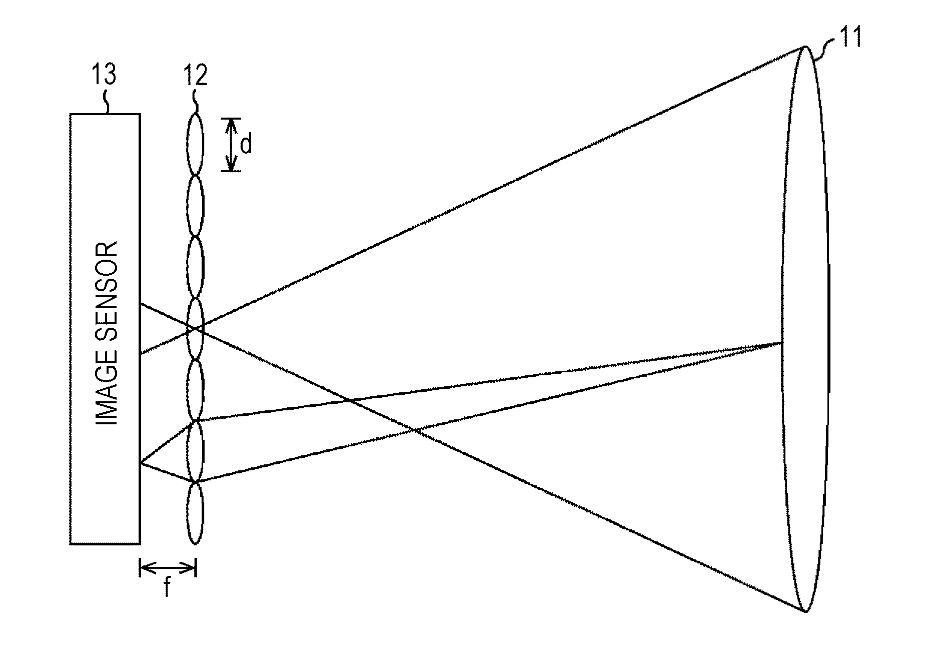
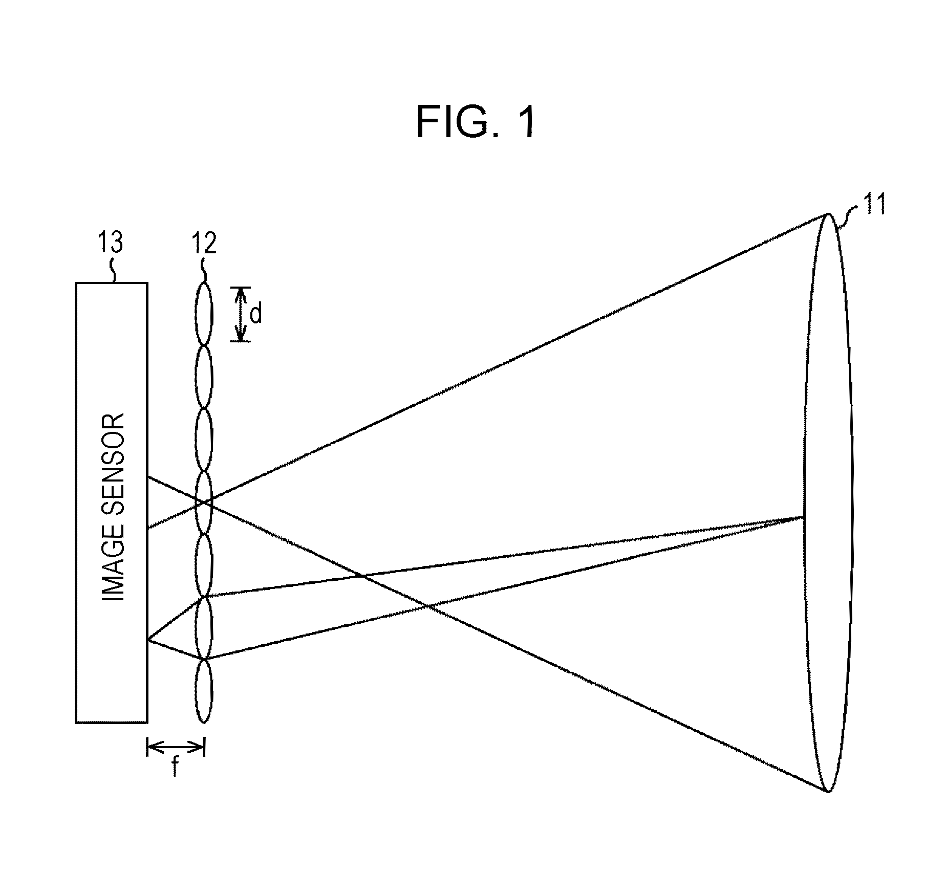
[0078]First, description will be made of a light field camera. A light field camera is an imaging apparatus using a technique called light field photography, such as described in Japanese Unexamined Patent Application Publication No. 2009-165115, for example. As illustrated in FIG. 1, a light field camera includes, for example, a main lens 11, a microlens array 12, and an image sensor 13 which receives incident light via the main lens 11 and microlens array 12 and performs photoelectric conversion thereof. As illustrated in FIG. 1, the microlens array 12 is provided at the focal position of the main lens 11, and the image sensor 13 is provided at the focal position of the microlens array 12.

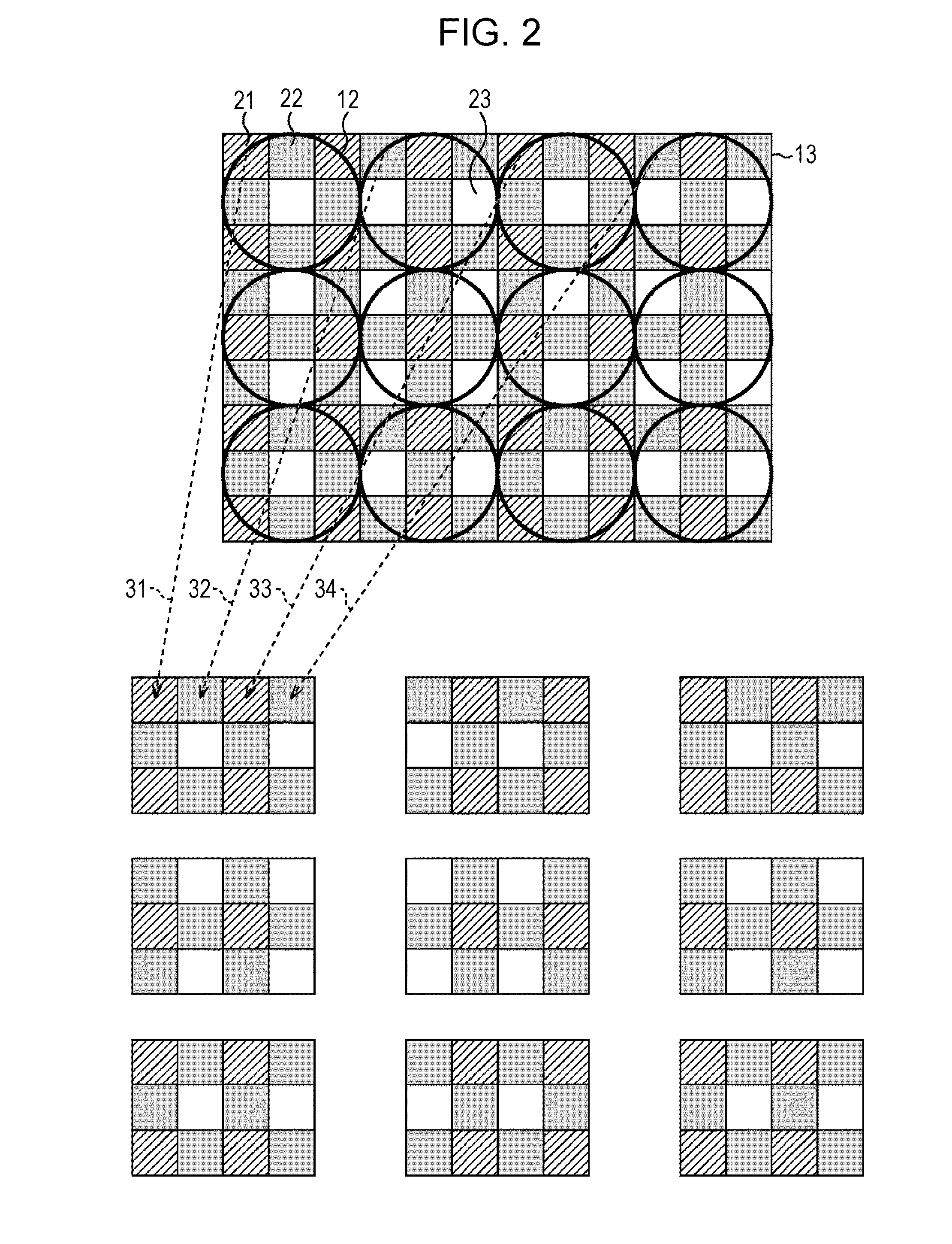
[0079]The microlenses of the microlens array 12 are each provided as to multiple pixels of the image sensor 13. An example of the relation between pixel groups of the image sensor 13 and the microlens array 12 is illustrated to the upper side of FIG. 2.

[0080]I...

second embodiment

2. Second Embodiment

Imaging Apparatus

[0339]The image processing device described above may be configured as a part of another device. For example, it may be an image processing unit built into an imaging apparatus.

[0340]FIG. 44 is a block diagram illustrating a primary configuration example of an imaging apparatus to which the present technology has been applied. As shown in FIG. 44, an imaging apparatus 700 is an imaging apparatus using a technique called light field photography, and is a so-called light field camera. The imaging apparatus 700 includes an optical unit 711, an image sensor 712, an A / D (Analog-to-Digital) converter 713, an operating unit 714, a control unit 715, an image processing unit 716, a display unit 717, a codec processing unit 718, and a recording unit 719.

[0341]The optical unit 711 is made up of a main lens, diaphragm, and so forth, and serves to adjust the focal point to the subject, collect light from the position where the focal point meets, and supplies ...

third embodiment

3. Third Embodiment

Personal Computer

[0352]The above-described series of processing can be carried out by hardware, or can be carried out by software. In this case, the above-described series of processing can be configured as a personal computer such as shown in FIG. 45, for example.

[0353]In FIG. 45, a CPU (Central Processing Unit) 801 of a personal computer 800 executes various types of processing, following programs stored in ROM (Read Only Memory) 802 or programs loaded from a storage unit 813 to RAM (Random Access Memory) 803. The RAM 803 also stores various types of data used by the CPU 801 to execute various types of processing, and so forth, as appropriate.

[0354]The CPU 801, ROM 802, and RAM 803, are connected one with another by a bus 804. An input / output interface 810 is also connected to this bus 804.

[0355]Also connected to the input / output interface 810 are an input unit 811 made up of an input device such as a keyboard or mouse or the like, or an input terminal or the li...


PUM


Abstract

An image processing device includes a viewpoint separating unit configured to separate multi-viewpoint image data, including images of multiple viewpoints and representing intensity distribution of light and the direction of travel of light according to positions and pixel values of pixels, into a plurality of single-viewpoint image data for each of the individual viewpoints; and a parallax control unit configured to control amount of parallax between the plurality of single-viewpoint image data obtained by separation into individual viewpoints by the viewpoint separating unit.

Description

BACKGROUND[0001]The present disclosure relates to an image processing device and method, a recording medium, and a program, and particularly relates to an image processing device and method, a recording medium, and a program, whereby stereoscopic effect of multi-viewpoint images can be controlled.[0002]Heretofore, various imaging apparatuses have been proposed and developed. Also, there have been proposed imaging apparatuses which perform predetermined image processing on imaged data obtained by imaging, following which the imaged data is output.[0003]For example, there has been proposed an imaging apparatus employing what is called “light field photography”, referred to as a “light field camera” (e.g., see Japanese Unexamined Patent Application Publication No. 2009-165115). This imaging apparatus includes an imaging lens, a microlens array, an imaging device, and an image processing unit, with an aperture diaphragm having a single aperture being provided to the middle portion of th...

Claims


Application Information

Patent Timeline
Patent Type & Authority Applications(United States)
IPC IPC(8): H04N13/02H04N5/21
CPCH04N13/0203H04N13/0011H04N13/0022H04N13/0228G06T2200/21G06T3/4053H04N2013/0081G06T7/0065G06T2207/10052G06T2207/20201H04N2013/0088G06T7/246G06T7/557H04N13/111H04N13/128H04N13/204H04N13/225H04N13/229H04N13/271G06T5/70G06T2207/10012
Inventor NAGUMO, TAKEFUMIMURAYAMA, JUNYAMAZAKI, TOSHIOTAMAYAMA, KEN
Owner SONY CORP
Learn More