
Method of producing composition having continuous phase and disperse phase dispersed finely in the continuous phase and apparatus for producing the compositon

a technology of disperse phase and composition, which is applied in the direction of biocide, animal repellents, other chemical processes, etc., can solve the problems of difficult to meet the demand of conventional emulsion production technology, difficult to control particle size accurately in conventional production methods, and low polydispersity of disperse phase particles, etc., to achieve high production efficiency and low cost

Inactive Publication Date: 2013-05-30
KYUSHU UNIV
View PDF1 Cites 10 Cited by
  • Summary
  • Abstract
  • Description
  • Claims
  • Application Information

AI Technical Summary

Benefits of technology

The present invention offers a method for producing a composition with a continuous phase and finely dispersed disperse phase, which has high production efficiency. This allows for the creation of a stable and uniform composition with low polydispersity, which can be useful in various technical applications.

Problems solved by technology

However, in emulsions produced by these methods, the size of their disperse phase particles was not uniform.
However, it was difficult to control the particle size accurately in conventional production methods.
Concerning a suspension polymerization method, there is a particularly strong demand for polymer fine particles having an intended, uniform size, but it was difficult for conventional technology of producing emulsions to satisfy the demand.
That is, in the axial-flow system, the supply speed of the disperse phase liquid was as low as 10−3 order level, which was not sufficient for practical use.
Another problem concerning the axial-flow system was that a higher supply speed than this level prevented the production of disperse phase particles having a uniform size; that is, the problem was that the polydispersity increased.
If a porous membrane is likely to get wet with a disperse phase liquid, the particles of the disperse phase generated on the surface of the porous membrane are unlikely to be released from the membrane and thus the supply speed of the disperse phase liquid cannot be increased.
However, Non-Patent Document 1 or 2 shows that since the disclosed method uses the asymmetrically structured porous glass membrane, a continuous phase liquid can pass oppositely through the membrane; thus, the membrane is unlikely to get wet with the disperse phase liquid and the particles of the disperse phase are likely to be released from the porous membrane, and this increased the supply speed of the disperse phase liquid.

Method used


Image

  • Method of producing composition having continuous phase and disperse phase dispersed finely in the continuous phase and apparatus for producing the compositon
  • Method of producing composition having continuous phase and disperse phase dispersed finely in the continuous phase and apparatus for producing the compositon
  • Method of producing composition having continuous phase and disperse phase dispersed finely in the continuous phase and apparatus for producing the compositon

Examples


example 1

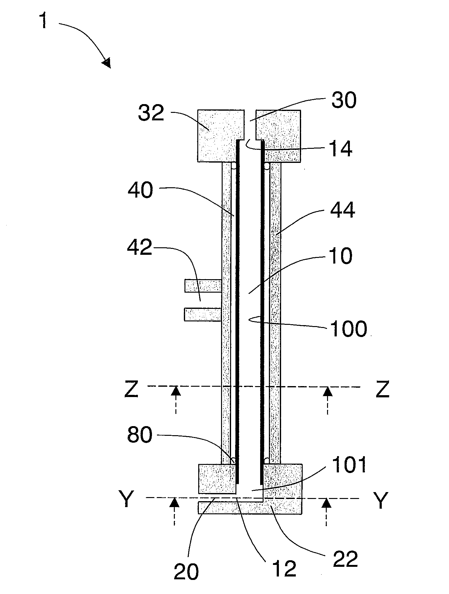
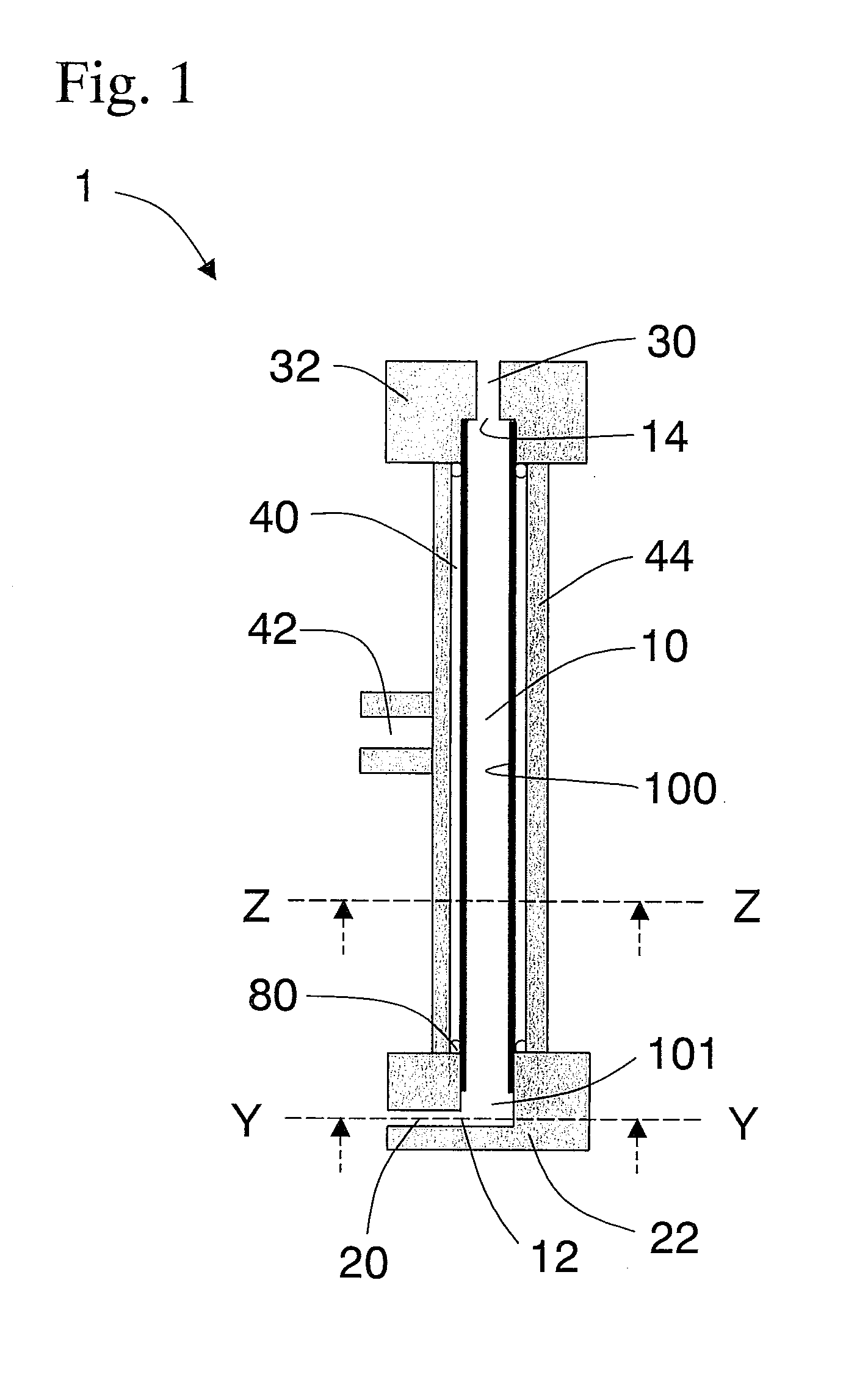
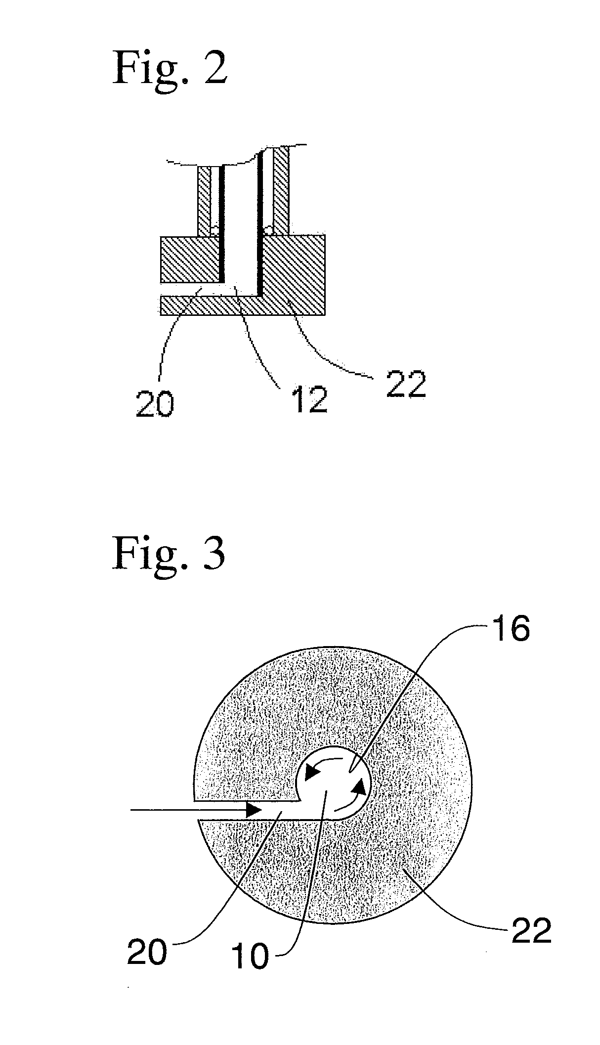
[0105]The cylindrical body prepared had the circumferential surface entirely formed by a Sirasu porous glass membrane (SPG membrane) having an average pore size of 5.2 μm and the cylindrical body was 10 mm in outer diameter, 9 mm in inner diameter, and 150 mm long (SPG Technology Co., Ltd.; SPG membrane; Lot No.: PJN08J14). Also prepared was a stainless steel cylindrical member 22 which was thicker than the cylindrical body using the SPG membrane, had the same inner diameter as that of the cylindrical body, and was closed at one end. As illustrated by FIG. 1, the member 22 was placed so that it capped the end of the cylindrical body using the SPG membrane to form a 5 mm-long cylindrical space the circumferential surface of which was formed by stainless steel at the end of the cylindrical body using the SPG membrane. A 155 mm-long cylindrical body 10 which had a porous portion 100 and a non-porous portion 101 was thus prepared. In the member 22, a through hole was created which was v...

example 2

[0109]The same procedure as in Example 1 was repeated to produce an emulsion and analyze it, except that the output of the pump was adjusted to set the flow linear velocity at 3.2 m / s. The distribution result of the relative particle mass is shown in FIG. 6. According to the result, the span was 0.64 and the average particle size was 21.3 μm.

example 3

[0110]The same procedure as in Example 1 was repeated to produce an emulsion and analyze it, except that the flow linear velocity was 6.4 m / s. The distribution result of the relative particle mass is shown in FIG. 6. According to the result, the span (polydispersity) was 1.21 and the average particle size was 16.2 μm.

[0111]According to the results obtained in Examples 1 to 3, when the flow linear velocity was 3.2 m / s, the span was the lowest. FIG. 7 shows the relation between the particle number and the particle size (the distribution of the relative particle number) for confirmation of the presence or absence of fine liquid particles (satellite liquid particles) generated in Examples 1 to 3. According to FIG. 7, the generation of fine liquid particles was not observed at the flow linear velocity of 3.2 m / s, whereas the generation of lots of fine liquid particles was demonstrated at the other linear velocities. This is consistent with the lowest polydispersity of the emulsion obtain...


PUM

PropertyMeasurementUnit
Fractionaaaaaaaaaa
Fractionaaaaaaaaaa
Fractionaaaaaaaaaa

Abstract

There is provided a method of producing a composition having a continuous phase and a disperse phase dispersed finely with low polydispersity in the continuous phase, with high production efficiency.The composition is produced by the production method including the steps of: (A) passing the swirling flow of the continuous phase liquid into a cylindrical body the circumferential surface of which is either in part or entirely formed by a porous membrane, (B1) supplying the disperse phase fluid to the swirling flow via the porous membrane to form the particles of the disperse phase on the porous membrane, and (B2) detaching the disperse phase particles formed on the porous membrane by the shear force of the swirling flow. The cylindrical body preferably has an inlet for the continuous phase liquid on the circumferential surface of the cylindrical body in the vicinity of one end of the cylindrical body and an inlet tube which extends from the inlet in the substantially vertical direction to the axis of the cylindrical body and the tangential direction to the cylindrical body. The step (A) is preferably carried out by use of the inlet tube to flow the continuous phase liquid in from the substantially vertical direction to the axis of the cylindrical body and the tangential direction to the inner wall surface of the cylindrical body.

Description

TECHNICAL FIELD[0001]The present invention relates to a method of producing a composition having a continuous phase and a disperse phase dispersed finely in the continuous phase and to an apparatus for producing the composition.BACKGROUND ART[0002]A known composition having a continuous phase and a disperse phase dispersed finely in the continuous phase is an emulsion having a continuous phase liquid and a disperse phase liquid dispersed finely in the continuous phase liquid or a microbubble composition having a continuous phase liquid and a disperse phase gas dispersed finely in the continuous phase liquid. A conventional emulsion has been produced by addition of a liquid which serves as a disperse phase and an emulsifier (e.g., a surfactant) to a liquid which serves as a continuous phase in order to form a mixed liquid which is then stirred mechanically to make the disperse phase finer. A known concrete means for the mechanical blending is stirrer, homogenizer, or colloid mill. An...

Claims


Application Information

Patent Timeline
IPC IPC(8): A61K9/14B01F3/08B01F17/00B01F25/46C09K23/00
CPCB01F3/0807C08F2/01B01F5/0476B01F5/0057B01F23/41B01F25/10B01F25/31421
Inventor SHIMODA, MITSUYA
Owner KYUSHU UNIV
Learn More