
Mr gamma hybrid imaging system

a hybrid imaging and gamma technology, applied in the field of nuclear imaging systems, can solve the problems of rf coils not being able to image, unable to place detectors in the area of large magnetic fields, and unable to detect artifacts or other mri image degradation

Active Publication Date: 2013-05-30
SCHELLENBERG JAMES
View PDF12 Cites 22 Cited by
  • Summary
  • Abstract
  • Description
  • Claims
  • Application Information

AI Technical Summary

Benefits of technology

The patent describes a magnetic resonance imaging (MRI)-compatible gamma camera that can be used to image breast tissue. The gamma camera is inserted through an opening in the MRI coil and is connected to a non-MRI compatible processing system. A patient lies on a table with a raised platform for the face and breasts, and an MRI image of the breast is generated using the MRI system. The gamma camera is then inserted through the opening in the MRI coil and a gamma image of the breast is generated. The MRI and gamma images are captured sequentially without moving or repositioning the patient. The technical effect of this invention is that it allows for accurate and precise imaging of breast tissue using both MRI and gamma cameras simultaneously.

Problems solved by technology

In this design, the detector could not be placed in the area of large magnetic fields because the materials and design used within the detector were adversely affected by magnetic fields, so light pipes connected the scintillator's optical output signals to the detectors which were outside the magnetic field area.
There has always been concern that introducing the metal collimator into the MRI bore during imaging would lead to imaging artifacts or other MRI image degradation.
If the physical collimator is positioned between the RF coil and the patient, then the RF coil will not be able to image.
For existing smaller bore superconducting magnets of 60 cm nominal bore size, this gamma camera design leads to 48 cm effective bore size, which is restrictive for some bariatric patients.
As well, for specific types of imaging positions and usages, such as human prone breast imaging, a hybrid MR-Gamma design such as this would have a gamma camera quite far from the breast, leading to a reduced sensitivity and accuracy.
For an application such as human prone breast imaging, this design also suffers from having a gamma camera which may be quite distant from the breast area.
It does not allow movement of the gamma camera into the magnetic field.
In this case, the effect of the collimator on the MR imaging is shown to cause changes to RF coil loading, and so adjustment of the coil trim capacitors is required.
Commercially available birdcage coils do not have such large rung spacings.
For human breast or brain imaging, and indeed for many human and animal imaging situations, including diagnostic, interventional and intra-operative imaging applications, it is not possible nor permissible to rotate the patient.
In human medical imaging applications it may also not be possible to rotate the coil.
For example, for brain imaging during brain surgery, the lower part of the head coil is usually fixed in place throughout the operation, and so rotation is not allowed.
To summarize, the previous work has shown a few MR gamma hybrid system designs that are focused on simultaneous imaging of the sample, with these systems not being optimized for some medical applications such as human breast imaging in the prone position using commercially available RF coils.
These existing designs require gamma compatible or specialized RF coils, and are not designed to interwork with existing commercially available RF breast coils.
The previous designs are limited because the collimator width is the same as the birdcage rung width.
The previous designs have not indicated any method whereby they could be removed for interventional tool or device access.
As well, for small gamma cameras that are used for lymph node imaging, there may be restricted access to the breast tail and underarm area.
If the RF coil and gamma camera are built together or fixed together in some way, then additional and multiple applications may not be possible.
If the coil and camera systems are built together in some way, then replacement of equipment elements may become more complex and more costly.

Method used


Image

  • Mr gamma hybrid imaging system
  • Mr gamma hybrid imaging system
  • Mr gamma hybrid imaging system

Examples


Embodiment Construction

[0045]Unless defined otherwise, all technical and scientific terms used herein have the same meaning as commonly understood by one of ordinary skill in the art to which the invention belongs. Although any methods and materials similar or equivalent to those described herein can be used in the practice or testing of the present invention, the preferred methods and materials are now described. All publications mentioned hereunder are incorporated herein by reference.

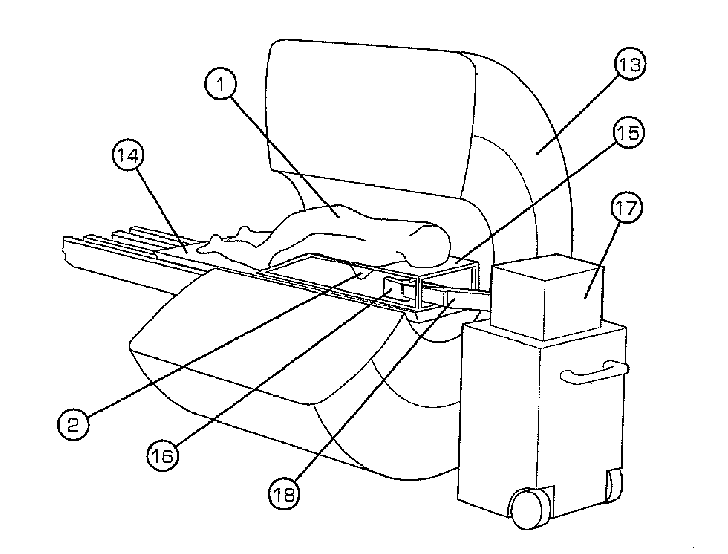
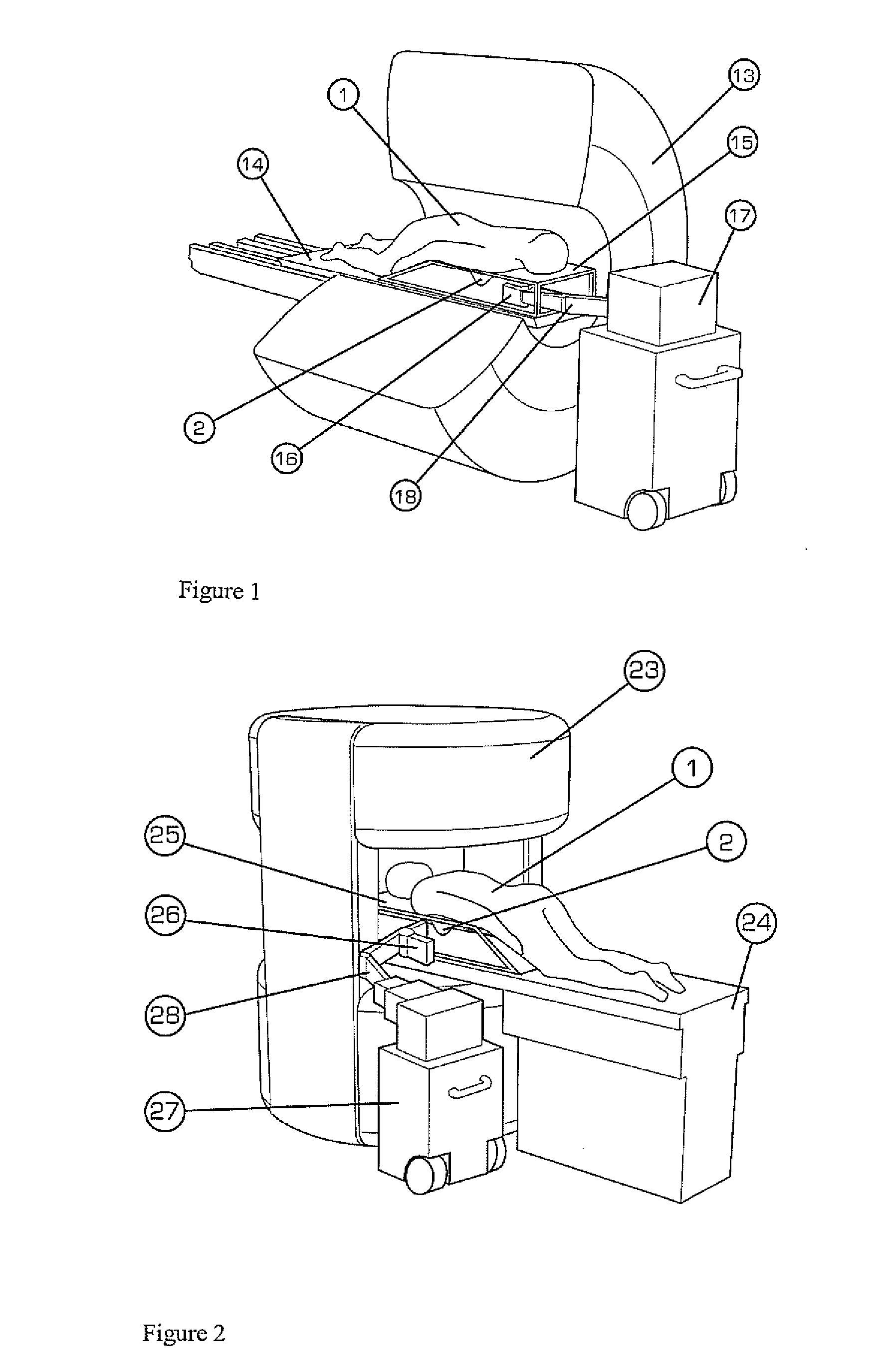
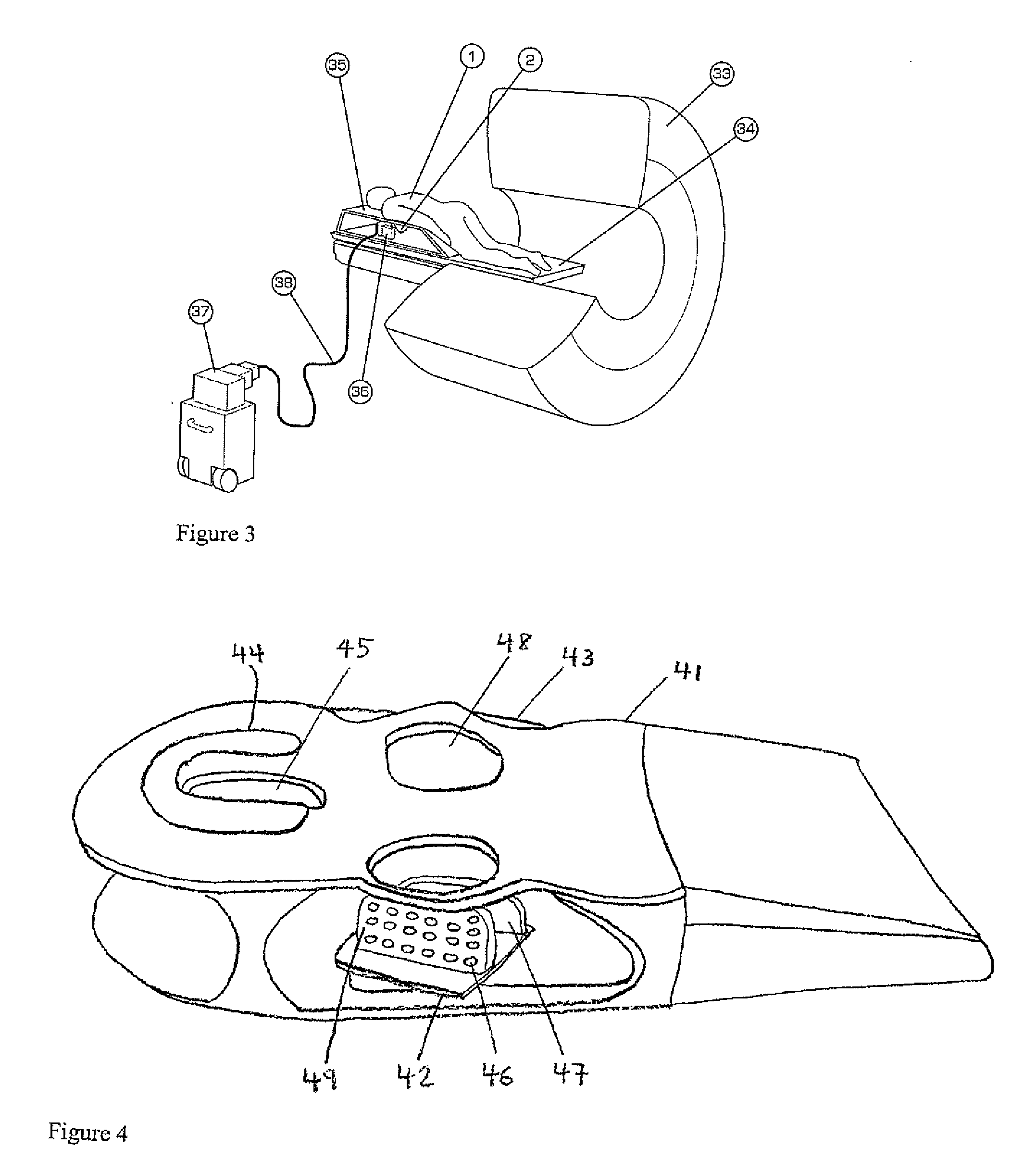
[0046]As discussed herein, there is provided a magnetic resonance imaging (MRI) compatible gamma camera comprising: an MRI-compatible gamma camera head arranged to be inserted through an opening in a MRI coil; a gamma shield; and a non-MRI compatible processing system connected to the gamma camera head by cabling.

[0047]The gamma camera head may comprise a collimator, a scintillator, a detector and an electronics assembly.

[0048]The gamma camera head may be substantially planar.

[0049]The gamma camera head may be connected to...


PUM


Abstract

A pendant breast imaging system that operates with a MRI system and which allows a planar gamma camera breast imaging system to be positioned away from the breast area while MRI imaging is occurring, and which then moves into breast imaging position after MRI imaging is complete, and which can again be removed from the breast area to allow intervention to occur is described. It may use various collimator or scintillator materials and designs.

Description

PRIOR APPLICATION INFORMATION[0001]The instant application claims the benefit of U.S. Provisional Patent Application 61 / 303,137, filed Feb. 10, 2010.BACKGROUND OF THE INVENTION[0002]There are two basic types of nuclear imaging systems for medical usage. Gamma imaging involves imaging one emission photon at a time, and collimators are usually part of the design. Positron imaging involves two emissions photons emitted in almost opposite directions, and collimators are not required as long as the detection system detects both photons. The invention of combined magnetic resonance imaging systems and nuclear medicine imaging systems began with U.S. Pat. No. 4,939,464 filed in 1989 by Hammer, which disclosed a combination NMR / PET scanner which uses light pipes to communicate the scintillation events to the exterior of the magnet. In this design, the detector could not be placed in the area of large magnetic fields because the materials and design used within the detector were adversely af...

Claims


Application Information

Patent Timeline
IPC IPC(8): A61B5/00A61B6/04A61B6/00A61B5/055
CPCA61B5/0555G01R33/481A61B5/418A61B6/0414A61B6/0435A61B6/107A61B6/4488A61B6/502A61B6/5247G01T1/1603A61B5/0035A61B5/4312A61B6/40A61B6/42A61B6/037A61B6/4405A61B6/4417G01R33/34046A61B5/415A61B5/055
Inventor SCHELLENBERG, JAMES
Owner SCHELLENBERG JAMES
Learn More