Piezoelectric resonator light-emitting-diode (LED) driving circuit

a driving circuit and resonant technology, applied in the direction of electroluminescent light sources, lighting apparatus, light sources, etc., can solve the problems of large supply of energy resources, increase cost and space occupied by circuits, and complicated circuit design, so as to reduce circuit costs and reduce switching power loss

Active Publication Date: 2013-06-06
MIDAS WEI TRADING +1
View PDF8 Cites 49 Cited by
  • Summary
  • Abstract
  • Description
  • Claims
  • Application Information

AI Technical Summary

Benefits of technology

[0008]A major objective of the present invention is to provide a piezoelectric resonant LED driving circuit. Wherein, a single switch replaces double switches of

Problems solved by technology

With the rising price of oil, the ample supply of energy resources is a most important issue.
However, the design and disposition of a full-bridge circuit having four switches and a half-bridge circuit having double switches could increase cost and space occupied by the circuit.
Also, the circuit design is rather co

Method used


Image

  • Piezoelectric resonator light-emitting-diode (LED) driving circuit
  • Piezoelectric resonator light-emitting-diode (LED) driving circuit
  • Piezoelectric resonator light-emitting-diode (LED) driving circuit

Examples


Embodiment Construction

[0021]The purpose, construction, features, functions and advantages of the present invention can be appreciated and understood more thoroughly through the following detailed description with reference to the attached drawings.

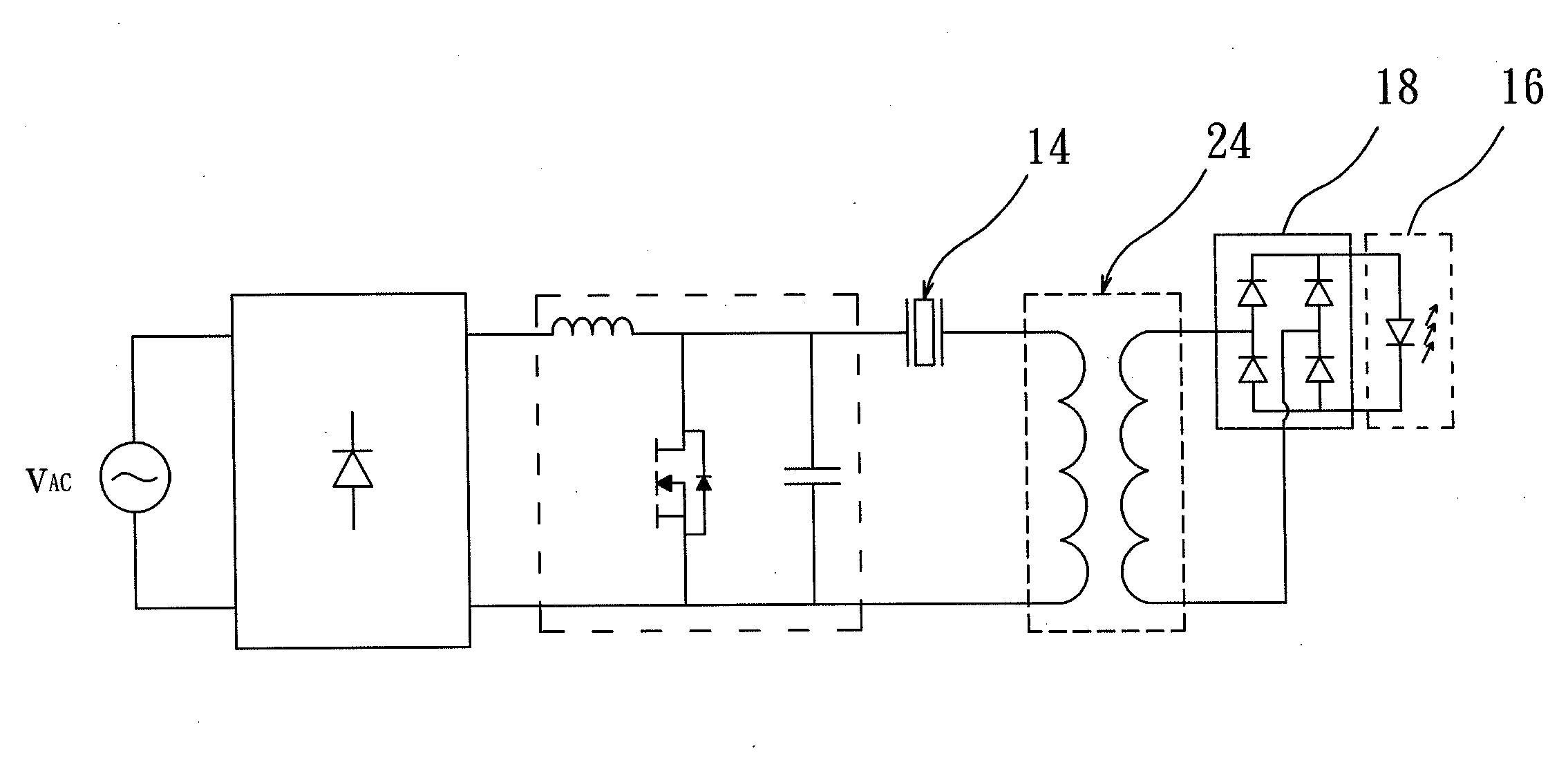
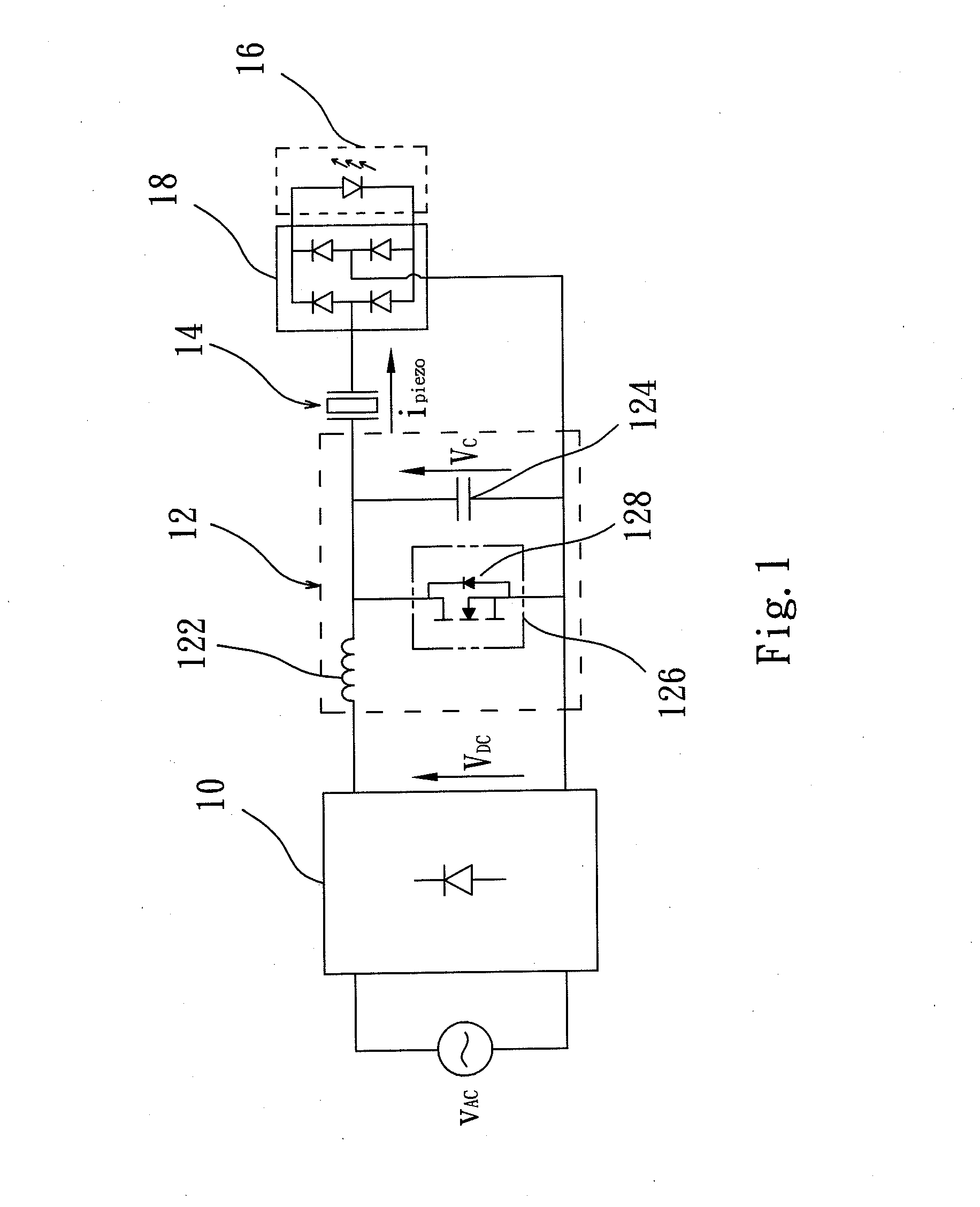
[0022]Refer to FIG. 1 for a circuit diagram of a piezoelectric resonant LED driving circuit according to a first embodiment of the present invention. As shown in FIG. 1, the piezoelectric resonant LED driving circuit includes a rectifier 10, a quasi-resonant switching module 12, a piezoelectric oscillator 14, and an LED module 16, and a rectifier circuit 18. The quasi-resonant switching module 12 is connected between the rectifier 10 and the piezoelectric oscillator 14, and the rectifier circuit 18 is connected between the piezoelectric oscillator 14 and the LED module 16. Wherein, the quasi-resonant switching module 12 includes an inductor 122, a capacitor 124, and a switch 126. The drain of the switch 126 is connected in parallel with the capacitor 124, and t...


PUM


Abstract

A piezoelectric resonant LED driving circuit, wherein a rectifier is used to rectify an AC voltage provided by the supply main into a DC voltage. Then, a quasi-resonant switching module performs resonance by means of the DC voltage to produce an induced current, to raise resonance frequency to operation frequency of a piezoelectric oscillator. Finally, the piezoelectric oscillator performs resonance and filtering using the induced current, to generate a sine wave current. Then, the sine wave current is rectified to output a DC current to drive an LED module.

Description

BACKGROUND OF THE INVENTION[0001]1. Field of the Invention[0002]The present invention relates to a piezoelectric resonant light-emitting-diode (LED) driving circuit, and in particular to a thin piezoelectric oscillator coupled with a single active switch to drive an LED.[0003]2. The Prior Arts[0004]With the rising price of oil, the ample supply of energy resources is a most important issue. Therefore, how to conserve energy and electricity is a critical task of the Industries. In this respect, lighting device occupying a very large proportion of energy consumption, has become an important item of energy conservation. Presently, the LED has been used widely as illumination device due to its advantages of high color saturation, mercury free, long service life, fast turn-on and turn-off speed, high illumination, low power consumption, light weight, thin profile, and compact size.[0005]Presently, piezoelectric transformer is used mainly to drive an LED circuit. Wherein, voltage of AC po...

Claims


Application Information

Patent Timeline
IPC IPC(8): H05B37/02H05B44/00
CPCH05B33/0815H05B37/02H05B45/3725H05B45/382H05B45/10
Inventor WEI, TAO-CHINLIU, YUAN-PING
Owner MIDAS WEI TRADING
Why Eureka
Try Eureka