Apparatus for collection of cathodoluminescence signals

a cathodoluminescence signal and apparatus technology, applied in the field of electromicroscopy, can solve the problems of 80% of tems installed worldwide that are unsuitable for known tem-cl technology, restricting the scope of view, and compromising the performance of tem when used for other analytical techniques, etc., to achieve high numerical aperture and optimize collection efficiency

Inactive Publication Date: 2013-06-06
GATAN INC
View PDF5 Cites 7 Cited by
  • Summary
  • Abstract
  • Description
  • Claims
  • Application Information

AI Technical Summary

Benefits of technology

[0007]In a further embodiment, the face of said fiber optic transmission cable is tilted to optimize collection efficiency. In a further embodiment, the fiber optic transmission cable is a single silica core high numeri

Problems solved by technology

However, this approach is restricted to TEM microscopes with a wide pole piece gap (e.g. >6 mm) and with an appropriate additional port to position the mirror above the specimen.
The use of a wide pole piece gaps compromise

Method used


Image

  • Apparatus for collection of cathodoluminescence signals
  • Apparatus for collection of cathodoluminescence signals
  • Apparatus for collection of cathodoluminescence signals

Examples


Embodiment Construction

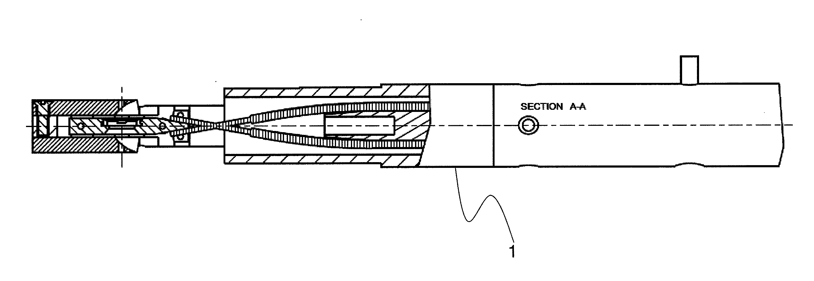
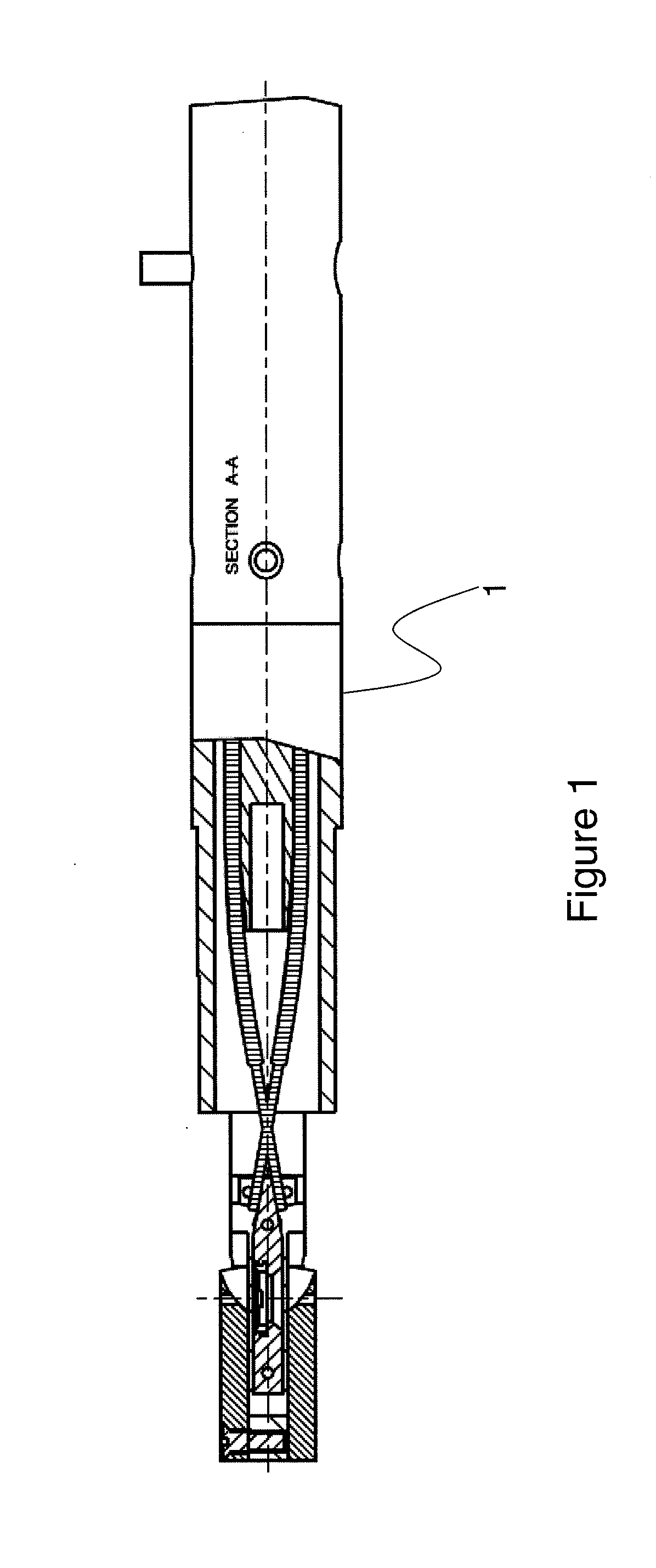
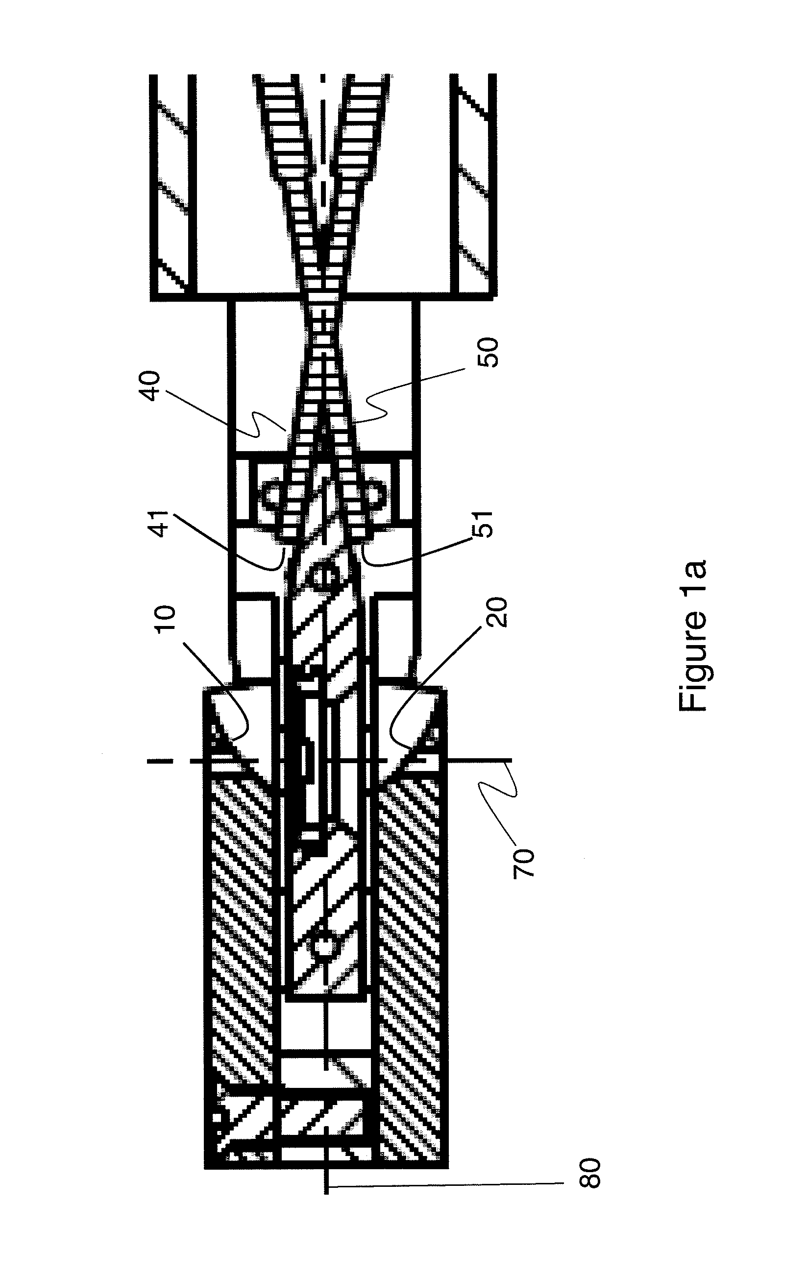
[0015]In an exemplary embodiment, and with reference to FIGS. 1 and 1a, collection mirrors 10, 20 attached to the end piece of a side entry holder 1 collect light from the region of the sample at the intersection of the holder center line 80 and the opening centerline 70 and transmit it to a suitable detection system external to the TEM via fiber optic cables 40, 50. The fiber optic cables have faces 41, 51 tilted for maximum collection of light.

[0016]The operation of the collection mirrors is as follows. With reference to FIGS. 2 and 3, Elliptical mirrors have two foci F1, F2. High collection efficiency requires a large solid angle subtended by the elliptical mirror 110, whilst efficient light coupling into the fiber 120 requires matching the numerical aperture of both the fiber and the mirror. Such a design typically occupies too much height and will not fit into the available space.

[0017]Through diligent efforts, the inventors have found that space occupied by the mirrors can be ...


PUM


Abstract

A side entry TEM holder incorporates a miniature tilted off axis elliptical mirror to collect cathodoluminescence from the specimen and couple it efficiently into a tilted fiber optic integrated into the holder. The design is compatible with the cryogenic operation of the holder. TEM specimens are partially transparent to the electron beam, and so light can be emitted above and below the specimen. The same principle of off-axis mirror and tilted fiber can be utilized to collect light from above and below the specimen yet fit into the very confined space required by insertion through the goniometer and for operation between narrow gap pole pieces. With a dual system, the emission of light from above the specimen can be compared to that from below thereby enhancing the versatility of the analytical technique.

Description

FIELD OF THE INVENTION[0001]This invention relates to the field of electron microscopy and in particular to the collection cathodoluminescence signals.BACKGROUND OF THE INVENTION[0002]Cathodoluminescence (CL) is more established as a technique in the scanning electron microscope (SEM) because of the larger signal and easier access to the specimen with regard to light collection optics. CL is of interest in the TEM (in STEM mode) because of the possibility of higher magnification work, higher kV studies, access to other complimentary analysis techniques, e.g. diffraction, EELS.[0003]Historically, efficient light collection of cathodoluminescence (CL) in a TEM has been achieved using off-axis parabolic mirrors which provide direct optical coupling through a side vacuum window. When the specimen is held at the focal point of these mirrors, light is then collimated and can be coupled to other transmission or detection apparatuses. However, this approach is restricted to TEM microscopes ...

Claims


Application Information

Patent Timeline
IPC IPC(8): G02B17/08G02B5/10
CPCH01J37/228H01J37/26H01J2237/2808H01J2237/2445H01J2237/24495H01J2237/20
Inventor GALLOWAY, SIMONSTOWE, DAVID J.VINCE, RICHARDBEECHING, LEVIBLACKWELL, JOHN
Owner GATAN INC
Why Eureka
Try Eureka