Safe cutting heads and systems for fast removal of a target tissue
a cutting head and target tissue technology, applied in the field of safe and efficient cutting heads, can solve the problems of increasing the pressure on the annulus, increasing the risk of delamination and damage of the annulus, and affecting the health of the intervertebral disc, so as to facilitate the entry of the target tissue and facilitate tissue removal. the effect of ease of removal
- Summary
- Abstract
- Description
- Claims
- Application Information
AI Technical Summary
Benefits of technology
Problems solved by technology
Method used
Image
Examples
example 1
Testing of Cutter Head Designs
[0089]A variety of cutter heads were tested in 3 cadaver laboratories on 28 discs. The results were compared to determine the most efficient cutter head design. A desirable cutter head design was one that would cut well on all target tissues, including the nucleus pulposus, vertebral endplates, and inner annulus tissue. However, the cutter head should also cut the target tissues in a desired manner while providing little to no damage to the perimeter tissue, such tissue including the perimeter annulus fibrosis tissue that should be preserved as a desirable perimeter structure. In addition, the design should remove tissue quickly under suction, such that the configuration of the head facilitates the removal of the tissue under suction.
[0090]FIGS. 9A-9G show cutting head designs that were tested, according to some embodiments. The design in FIG. 9A cut well but it was not as safe to the annulus as other designs. The design in FIG. 9B was safe to the annul...
example 2
[0091]This example further developed the designs of the cutting heads. The design in FIGS. 8G and 8H were further investigated in 7 cadaver labs and 28 discs.
[0092]FIGS. 10A-10E illustrate the advancements in the cutting head, according to some embodiments. The design in FIG. 10A shows a cutting head having a bevel on the outer surface of the cutting teeth, and the device cut poorly and gouged soft bone. The design in FIG. 10B shows an oval cutting head not having the bevel on the outer surface of the cutting teeth, and the device had inconsistent cutting and gouged soft bone. The design in FIG. 10C was shown for a comparison result using a ring curette, and the device gouged soft bone. The design in FIG. 10D shows a short cutting head with a single “talon” or pincer, and the device showed the most appealing results to date with optimal cutting and no gouging. FIG. 10E is another proposed design, configured to perform with the efficiency of the design of FIG. 10D, with the addition ...
example 3
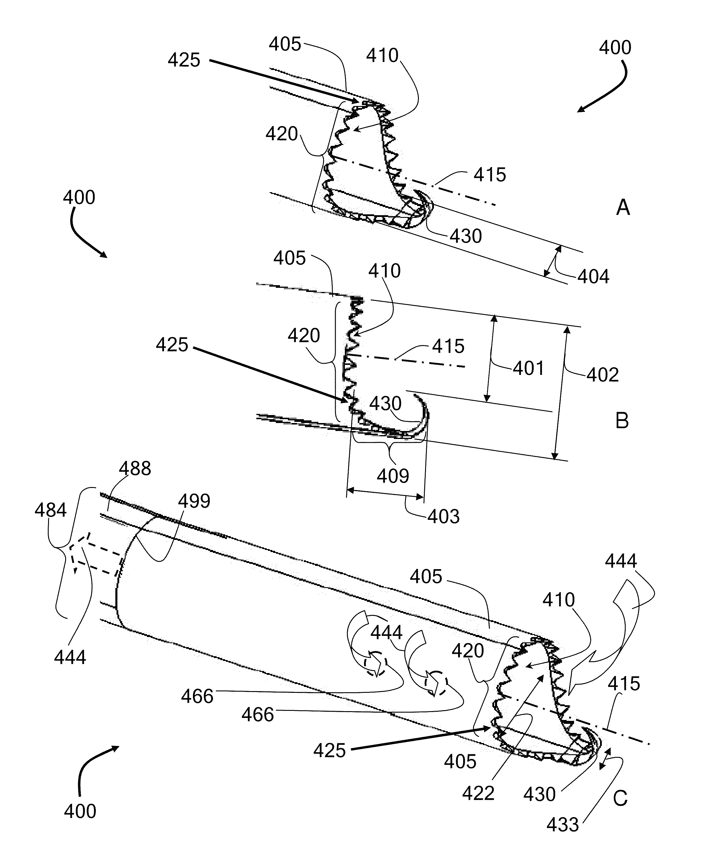
[0100]This example describes an alternate embodiment that was tested, referred to as the serpentine or bayonet configuration, in which the rigid suction tube 488 can have at least two angles; an angle θ1, and an angle θ3.
[0101]FIGS. 11A-11C illustrate a bayonet-type communication between a cutting head and a suction assembly, according to some embodiments. It was discovered that the distal end of the rigid suction tube 488 can be redirected in bayonet, or serpentine, fashion in order to facilitate an improved access of the cutting head to a target tissue during a discectomy, for example. As shown in FIGS. 11A-11C, Angles θ1 and θ3 can each be independently selected to range from about 0° to about 180°, with the limitation that (i) the net angle, θ4, that is realized between the central axis 415 of the lumen 410 of the cutting head 400 and the central axis 497 of the rigid suction tube 488 (extended as directed proximal to θ1) ranges from 0° to 90°; and, (ii) the distance 498 between...
PUM
 Abstract
Description
Claims
Application Information
 - R&D
- Intellectual Property
- Life Sciences
- Materials
- Tech Scout
- Unparalleled Data Quality
- Higher Quality Content
- 60% Fewer Hallucinations
Browse by: Latest US Patents, China's latest patents, Technical Efficacy Thesaurus, Application Domain, Technology Topic, Popular Technical Reports.
© 2025 PatSnap. All rights reserved.Legal|Privacy policy|Modern Slavery Act Transparency Statement|Sitemap|About US| Contact US: help@patsnap.com


