Discectomy kits with an obturator, guard cannula

a technology of discectomy kit and guard cannula, which is applied in the field of safe and efficient cutting head, can solve the problems of more compressive loading of the annulus, increased risk of delamination and damage of the annulus, and affecting the health of the intervertebral disc, so as to facilitate the entry of the target tissue and facilitate tissue removal. the effect of ease of removal

Active Publication Date: 2013-06-06
DEPUY SYNTHES PROD INC
View PDF29 Cites 12 Cited by
  • Summary
  • Abstract
  • Description
  • Claims
  • Application Information

AI Technical Summary

Benefits of technology

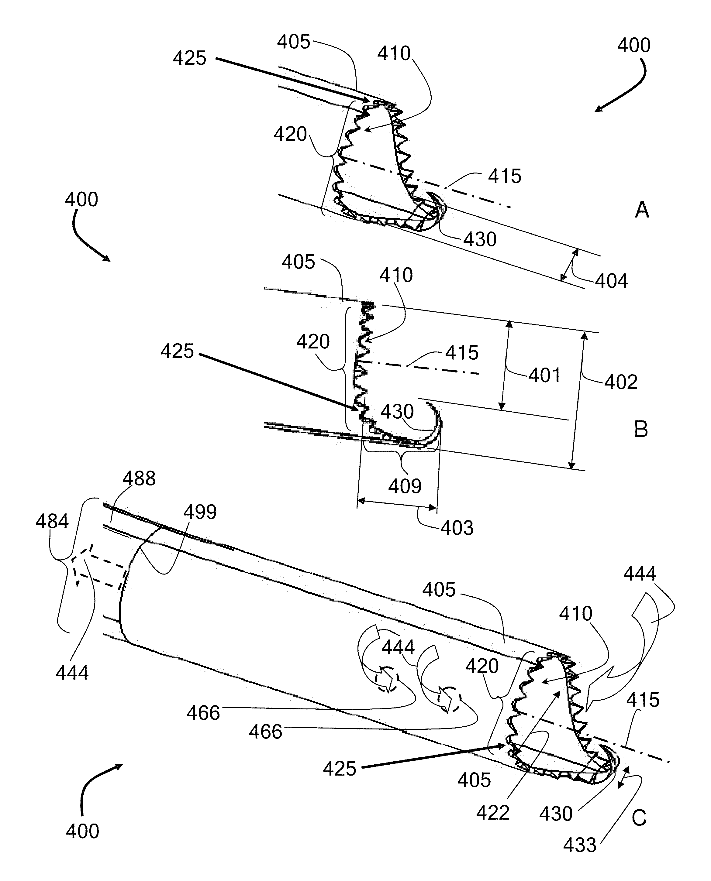
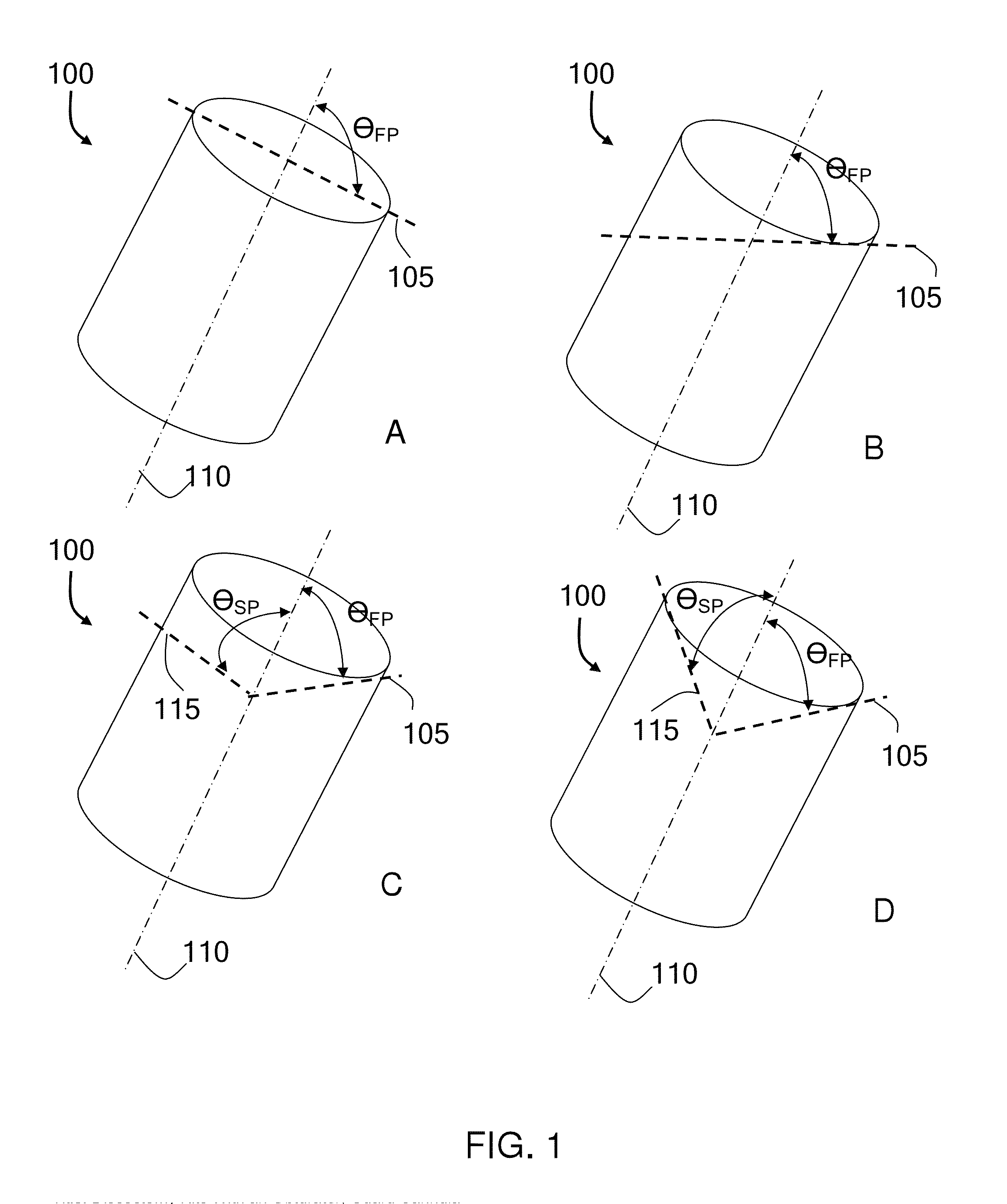
[0011]The cutting head can be tubular with a cutting surface forming at least a first plane on a distal perimeter of cutting head, the cutting head in operable communication with a suction device to excise a target tissue in a manner that facilitates an ease of removal of the tissue with the suction. The cutting surface can be flat, sinusoidal, or serrated, for example, and the first plane of the cutting surface may be at an angle, ΘFP, that deviates up to 75° from a position that is orthogonal to the central axis of the cutting head. In some embodiments, the cutting surface can have a second plane may be at an angle, ΘSP, that deviates up to 75° from a position that is orthogonal to the central axis of the cutting head. In some embodiments, the cutting head has a cutting blade and a blade guard for guarding a perimeter tissue from the cutting blade.
[0012]As such, the teachings include a tubular cutting head for removing a target tissue of a subject. In these embodiments, the cutting head can have an outer perimeter that circumscribes a lumen through the cutting head, the lumen having a central axis. The cutting head can also have a forward cutting blade on a distal edge of the outer perimeter, the forward cutting blade configured for (i) cutting a target tissue in a forward stroke of the cutting head and (ii) directing the cut tissue into the lumen. And, the cutting head can also have a blade guard positioned distal to the forward cutting blade and configured to guard a perimeter tissue from the forward cutting blade upon the forward stroke the blade guard having a width that is smaller than the width of a transverse cross-section of the lumen to facilitate entry of the target tissue into the lumen on the forward stroke.

Problems solved by technology

Intervertebral disc disease is a major worldwide health problem.
Loss of water binding by the nucleus results in more compressive loading of the annulus.
This renders the annulus more susceptible to delamination and damage.
Damage to the annulus, in turn, accelerates disc degeneration and degeneration of surrounding tissues such as the facet joints.
These procedures only address the symptom of lower back pain, nerve compression, instability and deformity.
This removal process is called a discectomy and is both tedious and frequently inadequate which can result in compromised fusion, as well as traumatic and time consuming due to the large incision and dissections required to expose the disc for discectomy.
This process can pose safety issues for tissues in between tool passage such as nerves.
Furthermore, disc debris left behind can hinder efficient subsequent tissue removal and insertion of the discectomy tools into the disc.
Tissue debris left behind can also compromise efficiency and effectiveness of the decortication resulting in a weaker fusion.
Moreover, corners inside the discs are often hard to reach by current state-of-the art tools, often leaving additional areas of inadequate disc removal.
In addition, state-of-the-art systems using a combination of suction and cutting suffer clogging problems due to excised tissue becoming lodged in the system.
Although several advanced tools have been developed, none have addressed all of these issues adequately.

Method used


Image

  • Discectomy kits with an obturator, guard cannula
  • Discectomy kits with an obturator, guard cannula
  • Discectomy kits with an obturator, guard cannula

Examples


example 1

Testing of Cutter Head Designs

[0089]A variety of cutter heads were tested in 3 cadaver laboratories on 28 discs. The results were compared to determine the most efficient cutter head design. A desirable cutter head design was one that would cut well on all target tissues, including the nucleus pulposus, vertebral endplates, and inner annulus tissue. However, the cutter head should also cut the target tissues in a desired manner while providing little to no damage to the perimeter tissue, such tissue including the perimeter annulus fibrosis tissue that should be preserved as a desirable perimeter structure. In addition, the design should remove tissue quickly under suction, such that the configuration of the head facilitates the removal of the tissue under suction.

[0090]FIGS. 9A-9G show cutting head designs that were tested, according to some embodiments. The design in FIG. 9A cut well but it was not as safe to the annulus as other designs. The design in FIG. 9B was safe to the annul...

example 2

[0091]This example further developed the designs of the cutting heads. The design in FIGS. 8G and 8H were further investigated in 7 cadaver labs and 28 discs.

[0092]FIGS. 10A-10E illustrate the advancements in the cutting head, according to some embodiments. The design in FIG. 10A shows a cutting head having a bevel on the outer surface of the cutting teeth, and the device cut poorly and gouged soft bone. The design in FIG. 10B shows an oval cutting head not having the bevel on the outer surface of the cutting teeth, and the device had inconsistent cutting and gouged soft bone. The design in FIG. 100 was shown for a comparison result using a ring curette, and the device gouged soft bone. The design in FIG. 10D shows a short cutting head with a single “talon” or pincer, and the device showed the most appealing results to date with optimal cutting and no gouging. FIG. 10E is another proposed design, configured to perform with the efficiency of the design of FIG. 10D, with the addition ...

example 3

[0100]This example describes an alternate embodiment that was tested, referred to as the serpentine or bayonet configuration, in which the rigid suction tube 488 can have at least two angles; an angle Θ1, and an angle Θ3.

[0101]FIGS. 11A-11C illustrate a bayonet-type communication between a cutting head and a suction assembly, according to some embodiments. It was discovered that the distal end of the rigid suction tube 488 can be redirected in bayonet, or serpentine, fashion in order to facilitate an improved access of the cutting head to a target tissue during a discectomy, for example. As shown in FIGS. 11A-11C, Angles Θ1 and Θ3 can each be independently selected to range from about 0° to about 180°, with the limitation that (i) the net angle, Θ4, that is realized between the central axis 415 of the lumen 410 of the cutting head 400 and the central axis 497 of the rigid suction tube 488 (extended as directed proximal to Θ1) ranges from 0° to 90°; and, (ii) the distance 498 between...


PUM


Abstract

Discectomy kits with obturator, guard cannulas are provided. The kits have a safe and efficient cutting heads for removing a target tissue from a subject during a surgical procedure are provided, the cutting heads composing a part of systems that address several problems, including clogging of state-of-the-art systems during removal of such tissue, for example. The target tissue can include any tissue that is accessible through a small surgical opening, for example, a joint tissue such as a meniscus or an intervertebral tissue, such as a nucleus pulposus. The devices can be referred to as orthopedic tissue removal devices having cutting heads associated with vacuum systems, making the systems useful in several procedures, including X-LIF (lateral approach to an intervertebral fusions) procedures, T-LIF (transforaminal approach to intervertebral fusions) procedures, P-LIF (posterior approach to intervertebral fusions), and a percutaneous, transforaminal approach (Kambin triangle access).

Description

CROSS-REFERENCE TO RELATED APPLICATIONS[0001]This application claims the benefit of U.S. Provisional Application No. 61 / 566,629, filed Dec. 3, 2011, and U.S. Provisional Application No. 61 / 596,865, filed Feb. 9, 2012, each application of which is hereby incorporated herein by reference in its entirety.BACKGROUND[0002]1. Field of the Invention[0003]The teachings provided herein are generally directed to a safe and efficient cutting head for removing a target tissue from a subject during a surgical procedure.[0004]2. Description of the Related Art[0005]Intervertebral disc disease is a major worldwide health problem. In the United States alone almost 700,000 spine procedures are performed each year and the total cost of treatment of back pain exceeds $30 billion. Age related changes in the disc include diminished water content in the nucleus and increased collagen content by the 4.sup.th decade of life. Loss of water binding by the nucleus results in more compressive loading of the ann...

Claims


Application Information

Patent Timeline
Patent Type & Authority Applications(United States)
IPC IPC(8): A61B17/32
CPCA61B17/320016A61B2017/00261A61B2017/00738A61B2019/481A61F2002/444A61B17/32002A61B2017/320064A61B17/3205A61F2/44A61B2217/002A61B2090/08021
Inventor TO, JOHN
Owner DEPUY SYNTHES PROD INC
Why Eureka
Try Eureka