Hollow fiber membrane module with miniskeins in miniheaders having a zig-zag configuration

a technology of hollow fiber membrane and miniskeins, which is applied in the field of modules of microporous hollow fiber membrane, can solve the problems of impeded filtration, high cost of using the module, and little indication, and achieve the effect of saving the cost of operation of the filtration process and efficient use of air

Active Publication Date: 2013-06-13
LOTTE CHEM CORP
View PDF11 Cites 17 Cited by
  • Summary
  • Abstract
  • Description
  • Claims
  • Application Information

AI Technical Summary

Benefits of technology

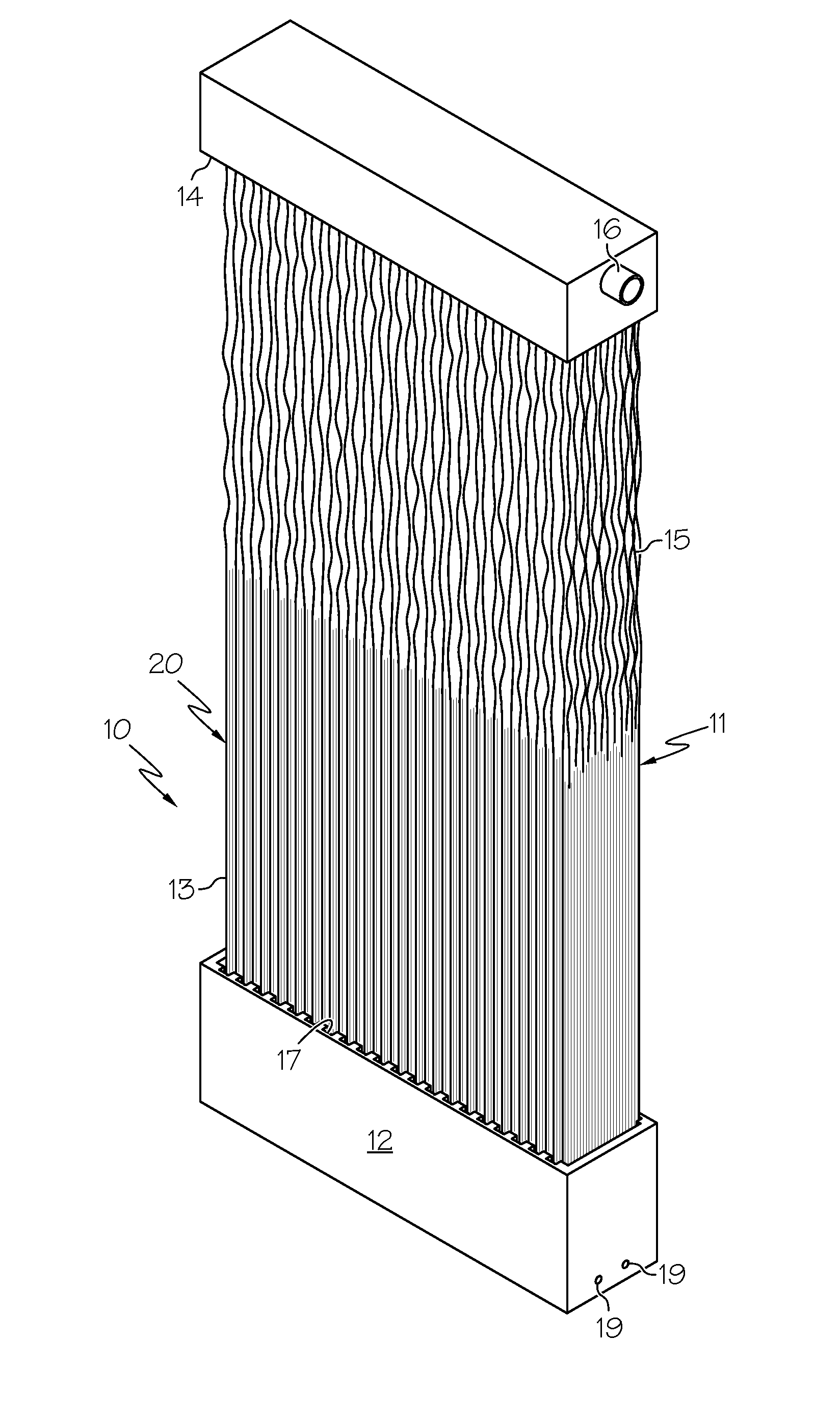
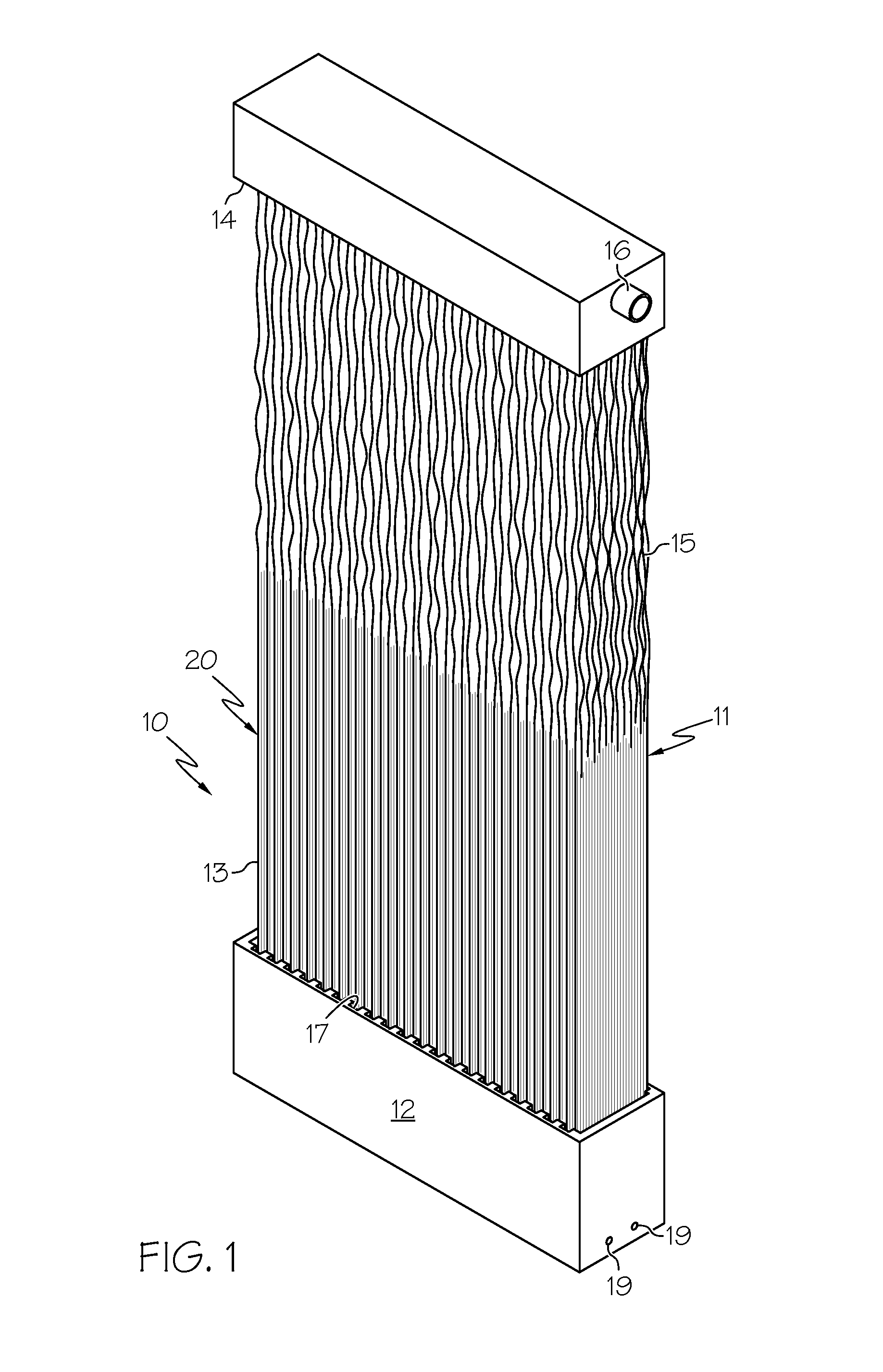
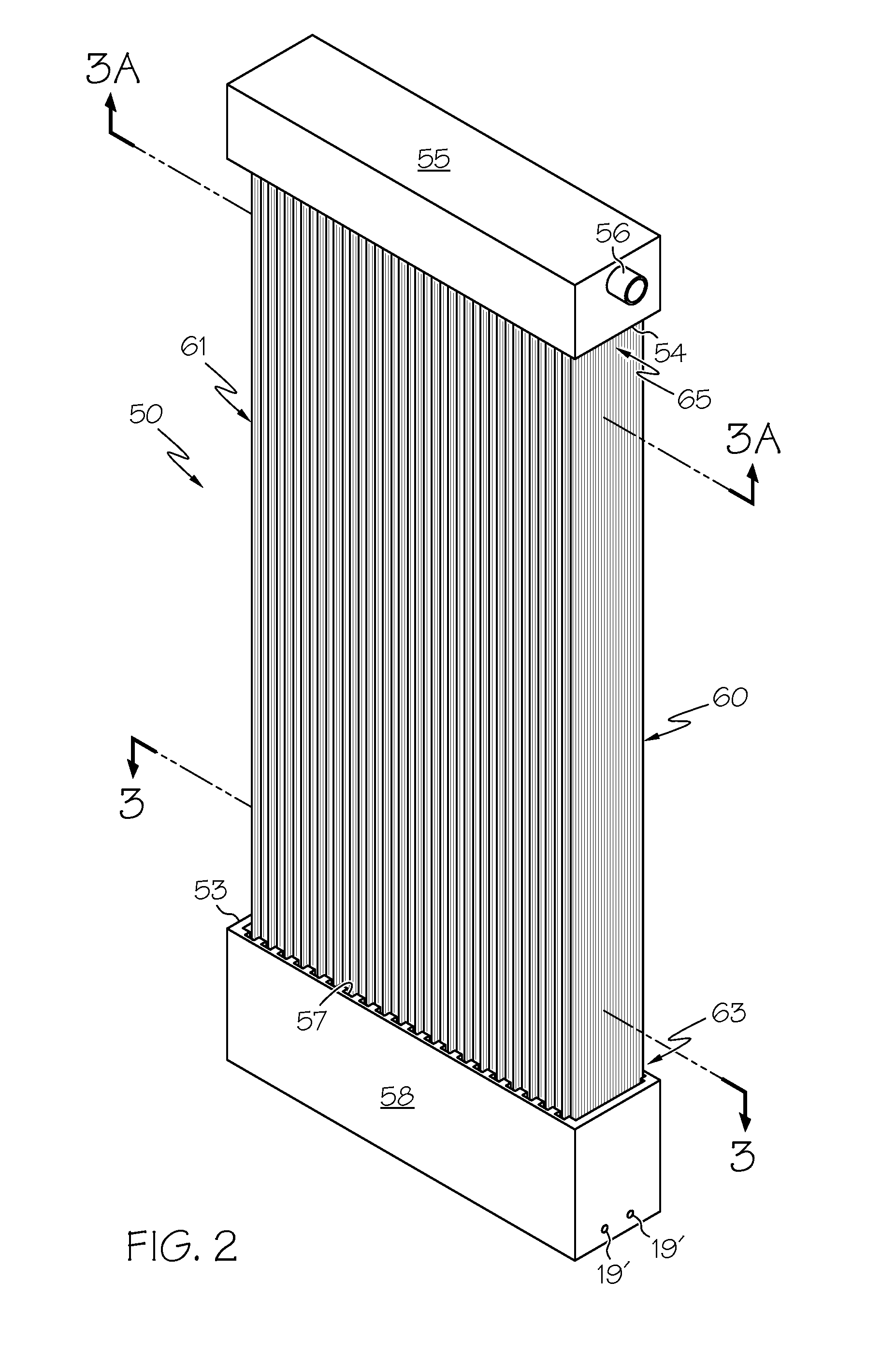
[0046]When held relatively taut and substantially vertical, the fibers of a miniskein permit operation with a volumetric packing density δv higher than that possible with a prior art skein in which the length of fibers is >5% longer than the fixed distance between the upper and lower headers. The zig-zag configuration allows for the efficient use of air; and as a result, the differences in performance between this module and a prior art module with a longitudinally spaced apart subdivided skein, translates into unexpectedly high savings in the cost of operation of the filtration process.
[0047]It has been discovered that an effective packing density δhe, lower than that typically deemed optimum in the headers of a typical prior art module is surprisingly more effective when the lower δhe is achieved by dividing the fibers of a skein so that it is subdivided into multiple miniskeins, each with its own lower non-potted miniheader, the packing density δh of fibers on each lower miniheader being greater than 25%.

Problems solved by technology

Without such scrubbing action, suspended solids in the wastewater would build up on the surfaces of the fibers and around them, and greatly impede filtration.
However, the more open a skein, the lower is the surface area of fibers per unit volume of substrate in which the module is deployed, and the higher the cost of using the module.
The prior art has devoted much effort towards configuring a module for a commercially viable process, but has provided little indication as to which features in a module coax the maximum efficiency from a chosen skein of fibers.
The longer the fibers, the more they sway, and the greater the likely damage.
Damaged fibers leak.
At the upper end of the range, the slack in the fibers may cause damage due to rubbing against each other, and at the lower end of the range, risk breakage due to being overstretched.
One cannot predict performance of a skein from its volumetric packing density.
To improve the performance one might consider decreasing δv to allow more space between fibers, not increasingδv, which would provide opportunities for fibers to scrub against each other, and increases the chance of one or more fibers being damaged.

Method used


Image

  • Hollow fiber membrane module with miniskeins in miniheaders having a zig-zag configuration
  • Hollow fiber membrane module with miniskeins in miniheaders having a zig-zag configuration
  • Hollow fiber membrane module with miniskeins in miniheaders having a zig-zag configuration

Examples


first embodiment

[0085]In a miniheader, the lower portions of a first pair of arrays are securely adhered to a fiber-mounting strip. The term “strip” refers to a laminar, heat-stable, rigid material of arbitrary length, cut to length as needed, which will not bend during operation of the module sufficiently to have a lower miniheader come out of the slots in the aerator box in which the miniheader is mounted. The strip has a generally uniform width in the range from about 0.5 cm-5 cm, preferably 1-3 cm wide, and uniform thickness in the range from about 0.5 mm-5 mm, preferably 1 mm-2 mm thick, depending upon the diameter and number of fibers to be used in an array, the type of adhesive used, and the tensile strength at yield, hardness and impact strength of the material. Preferred is a synthetic resinous material such as a lower C2-C4 polyolefin, PVC or ABS, which material has a tensile strength @ yield (ASTM D638) of at least 40 MPa; a hardness of at least 50 Shore D (ASTM D2240); and impact streng...

second embodiment

[0088]In a miniheader, each array is adhesively secured, back-to-back, preferably with a meltable adhesive ribbon, and without a fiber-mounting strip. The opposed skein-mounting means is provided with individual skein-mounting tabs (referred to as “mounting tabs”). The mounting tabs may be provided with either (i) opposed stub-strips to each of which an end-portion of an array is adhesively secured so that the stub-strips are integrated into the miniheader, or (ii) separate, individual T-pins inserted behind fibers in arrays near opposed ends of a miniheader, after it is formed. The individual T-pins are preferably non-removably secured within the lower portion of a miniskein for up-and-down movement in the box. Whether stub-strips or T-pins, such mounting tabs are held in opposed vertical slots in the longitudinal walls of the box, and are movable upward when the fibers contract longitudinally, preventing them from breaking.

[0089]Irrespective of how the upper portions of the fibers...

third embodiment

[0119]a miniheader is without a mounting strip and without stub-strips. In this embodiment, a miniheader is assembled as follows: A continuous fiber is wound onto the non-stick surface of a sb-roller in cooperation with an intermediate roller to form a first layer of wound fiber onto which a strip of meltable adhesive is pressed. The continuous fiber is cut, and a second layer of fiber is wound onto the sb-roller, directly above the first wound layer, and a strip of meltable adhesive is pressed onto it before the fiber is cut. Additional layers of fiber may be wound onto the sb-roller, each being adhered to the one beneath it, as before, to form a stack of fibers which is cut from the sb-roller to provide multiple miniheaders without a mounting means.

[0120]Before each miniheader is mounted in slotted box 48 or 48′ (see FIGS. 14 and 14A), the arms of T-shaped mounting pins 66′, 66″ are inserted behind end arrays (see FIG. 7A), near each end of the miniheader, to provide a mounting me...


PUM

PropertyMeasurementUnit
included angleaaaaaaaaaa
thicknessaaaaaaaaaa
diameteraaaaaaaaaa

Abstract

A module of hollow fiber membranes is re-configured to break up and rearrange a skein into multiple miniskeins each having no more than 250 fibers, all lower miniheaders of the miniskeins being slidably held for vertical movement in vertical slots in an aerator box. Upon shrinkage of the fibers, the lower miniheaders rise in the box. Each miniskein has from 2-12 planar ordered arrays in which the fibers are adhesively secured, preferably without potting the lower miniheaders. The lower ends of the fibers are dead-ended and lower miniheaders are positioned sequentially, transverse to the longitudinal axes of the upper header and the aerator box; its upper miniheader is potted in a choice of configurations. This configuration of miniskeins provides a packing density in each miniheader, whether upper or lower, not attainable in a prior art skein; the use of an aerator box having an area (footprint) no greater than 35% of that of the upper header, provides an effective packing density in the aerator box which provides exceptionally effective use of sparging air and readily removable sludge which drops through the bottom of the aerator box.

Description

FIELD OF THE INVENTION[0001]This invention relates to a module of microporous hollow fiber membranes (“fibers” for brevity) used to purify water in a tank in which the module is immersed. A typical module comprises a skein of a multiplicity of tubular membranes, usually thousands, the upper and lower ends of which are potted in upper and lower headers respectively. Because the skein is not enclosed, such modules are referred to as “shell-less” modules which rely on air, sparged from near, and / or below, the lower header, to cleanse the fibers of wet solids being deposited on the fibers' surfaces. More specifically, the invention relates to shell-less modules in which the skein of fibers provide microfiltration and ultrafiltration of a fluid, typically water, held in a tank under atmospheric pressure.BACKGROUND OF THE INVENTION[0002]Multiple modules, often assembled in a cassette, are deployed in a tank of fluid to be filtered, e.g. water, or wastewater with suspended solids, either f...

Claims


Application Information

Patent Timeline
Patent Type & Authority Applications(United States)
IPC IPC(8): B01D63/02
CPCB01D63/021B01D63/024B01D63/026Y10T29/49826B01D2313/025B01D2313/21C02F3/1273B01D63/043Y02W10/10B01D63/02B01D63/04B01D65/02B01D67/00C02F1/44
Inventor SUK, DANIEL EUMINE
Owner LOTTE CHEM CORP
Why Eureka
Try Eureka