
Radiographic device, radiographic system, control method and recording medium for radiographic device

a radiographic device and radiographic system technology, applied in the direction of material analysis using wave/particle radiation, instruments, applications, etc., can solve the problems of excessive dose, subject undergoes unnecessary exposure accordingly, image quality of x-ray image deterioration,

Active Publication Date: 2013-06-13
FUJIFILM CORP
View PDF13 Cites 26 Cited by
  • Summary
  • Abstract
  • Description
  • Claims
  • Application Information

AI Technical Summary

Benefits of technology

The present invention is about a radiographic device and system that can reduce excessive dose caused by delay in stopping irradiation of radiation during AEC process. The technical effect of the invention is that it sends a stop timing notification to the radiation generation device before the stop timing reaches, even if there is a delay in the AEC process. This ensures that irradiation of radiation stops around the stop timing, thus reducing the excessive dose caused by the delay.

Problems solved by technology

The first method has a problem in that the pre-irradiation is necessary and thus a subject undergoes an unnecessary exposure accordingly.
However, in the second method, since AEC is performed during irradiation of X rays, in a case where the AEC process is delayed, a cumulative dose exceeds a dose target value and thus an excessive dose is generated.
Therefore, there is a problem in that image quality of an X-ray image deteriorates or a subject undergoes an unnecessary exposure due to the excessive dose.
If the AEC processes are delayed, the timing for stopping the irradiation of X rays in the X-ray generation device also becomes late.
However, even in the wired manner, in a case where a relay device such as a switching hub or a router is interposed in the middle of the communication path, there is concern that, when a process load on the relay device is large, a communication rate is reduced, or when the relay device is frozen, the communication path is instantaneously interrupted.

Method used


Image

  • Radiographic device, radiographic system, control method and recording medium for radiographic device
  • Radiographic device, radiographic system, control method and recording medium for radiographic device
  • Radiographic device, radiographic system, control method and recording medium for radiographic device

Examples


first embodiment

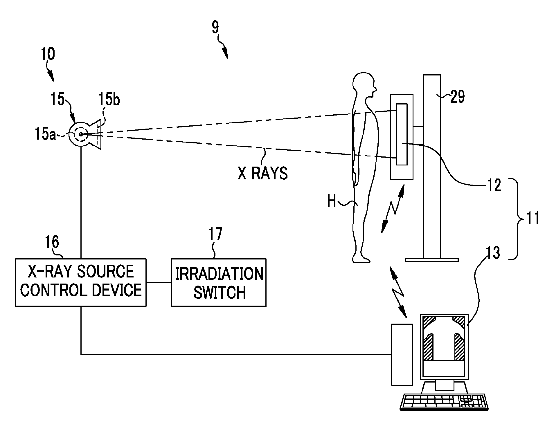
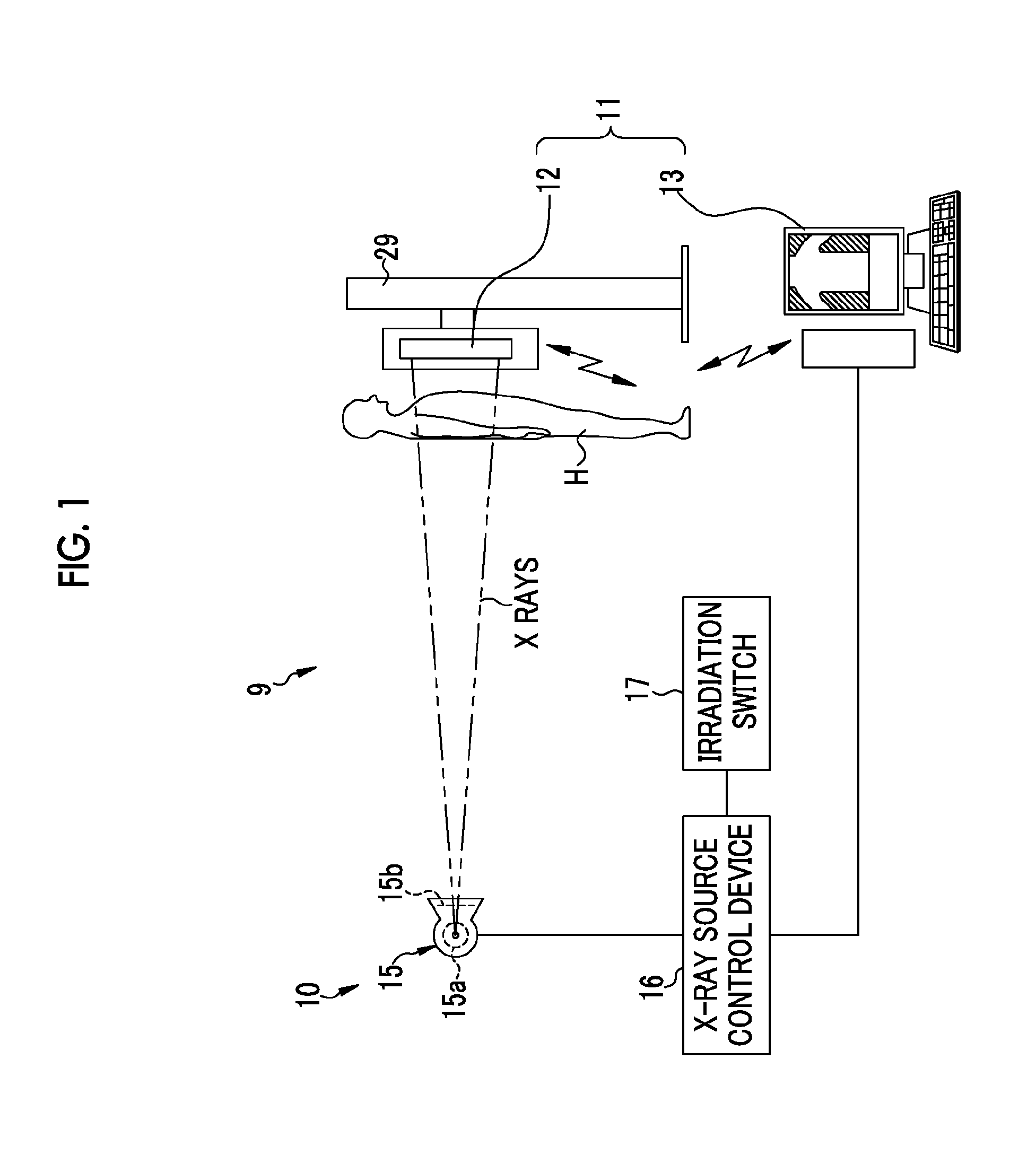
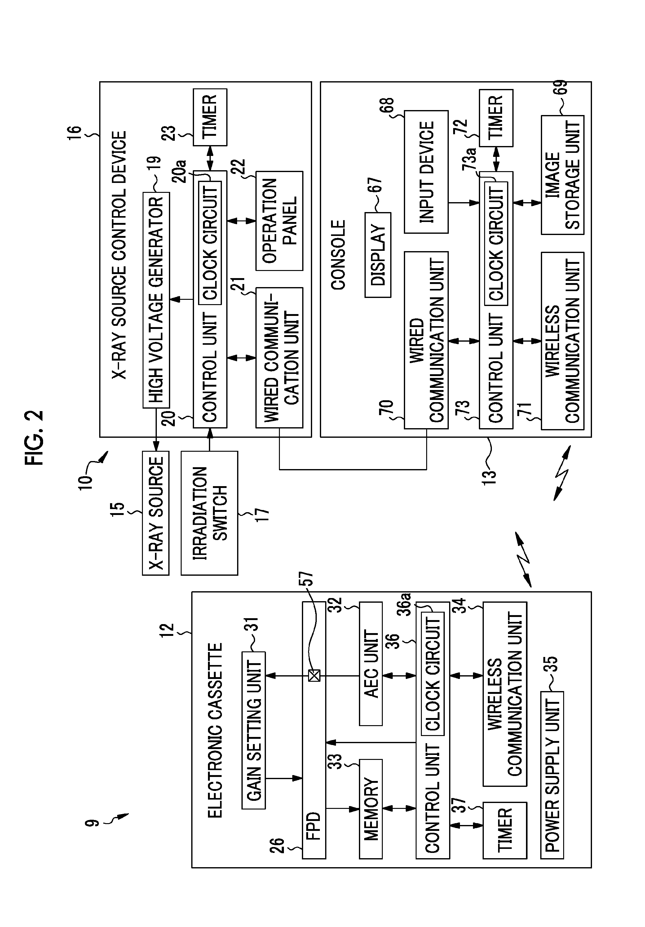
[0081]As illustrated in FIG. 1, an X-ray radiographing system 9 of the present invention includes an X-ray generation device (radiation generation device) 10 which generates X rays, and an X-ray radiographing device (radiographic device) 11 which receives X rays transferred through a subject H and radiographs an X-ray image of the subject H. The X-ray radiographing device 11 includes an electronic cassette 12 which detects an X-ray image, and a console 13 which controls the electronic cassette 12 and performs an image process on an X-ray image. In the X-ray radiographing system 9 of the present embodiment, the X-ray generation device 10 and the console 13 are connected so as to communicate with each other in a wired manner using a communication cable, and the electronic cassette 12 and the console 13 are connected so as to communicate with each other in a wired manner using electric waves. In addition, the console 13 is not essential, and the X-ray radiographing device 11 may be ind...

second embodiment

[0164]Although, in the first embodiment, an example in which sending of the stop timing notification STN is awaited up to the time point t2 which is the predetermined time TL earlier than the scheduled stop time te after the AEC process finishes has been described, the stop timing notification STN may be sent at the time point t1 when the AEC process finishes as in the second embodiment illustrated in FIGS. 11 to 13. Description of the common parts to the first embodiment, and the description will be made mainly based on differences.

[0165]As illustrated in FIG. 11, in a case of the second embodiment, the electronic cassette 12 sends the stop timing notification STN at the time point t1 when prediction of the scheduled stop time te is completed in the AEC process. For this reason, the stop timing notification STN arrives at the X-ray source control device 16 at the time point t1′ which is the predetermined time TL later than the time point t1. In a case where the time from the time p...

third embodiment

[0183]The third embodiment illustrated in FIG. 19 is an example where the stop timing notification STN is retransferred after irradiation of X rays starts until the irradiation stops, that is, until a cumulative dose reaches a dose target value. The example illustrated in FIG. 19 is an example in which transmission is retried in a case where the stop timing notification STN sent by the electronic cassette 12 does not arrive at the X-ray source control device 16 due to instantaneous interruption of the communication path or time-out when a time lag of communication is long.

[0184]In FIG. 19, the electronic cassette 12 performs the AEC process, and sends the stop timing notification STN at the time point t11. At the first transmission timing, a case where the stop timing notification STN does not arrive at the X-ray source control device 16 due to instantaneous interruption of the communication path or the like is illustrated. The electronic cassette 12 retries transmission of the stop...


PUM

PropertyMeasurementUnit
timeaaaaaaaaaa
timeaaaaaaaaaa
time lagaaaaaaaaaa

Abstract

An AEC unit of an electronic cassette sets a dose target value and a short-circuited pixel used for AEC based on a radiographing condition. When a control unit of the electronic cassette detects start of irradiation of X rays, the AEC unit starts integration of a cumulative dose of X rays which are incident to a target region based on a dose detection signal output by the short-circuited pixel. The AEC unit predicts a stop timing at the time point t1, waits until the time point t2 which is a predetermined time earlier than a scheduled stop time, and sends a stop timing notification to an X-ray generation device at the time point t2. When the stop timing notification is received, a X-ray source control device immediately inputs an irradiation stop command so as to stop an operation of an X-ray source.

Description

BACKGROUND OF THE INVENTION[0001]1. Field of the Invention[0002]The present invention relates to a radiographic device which radiographs a radiological image from radiation transferred through a subject, a radiographic system using the radiographic device, and a control method and a recording medium for the radiographic device.[0003]2. Description of the Related Art[0004]In a medical field, an X-ray radiographing system using radiation, for example, X rays, is known. The X-ray radiographing system includes an X-ray generation device which has an X-ray source generating X rays, and an X-ray radiographing device which receives irradiation of X rays generated by the X-ray source and transferred through a subject and radiographs an X-ray image indicating image information of the subject.[0005]The X-ray radiographing device includes an X-ray image detection device and a console. An X-ray image detection device which uses a flat panel detector (FPD) instead of an X-ray film or an imaging ...

Claims


Application Information

Patent Timeline
Patent Type & Authority Applications(United States)
IPC IPC(8): H05G1/42G01N23/04
CPCH05G1/42G01N23/04A61B6/4283A61B6/56A61B6/542A61B6/5294
Inventor TAJIMA, TAKASHI
Owner FUJIFILM CORP
Learn More