Method for connecting a fibre composite component to a structural component of an aircraft and spacecraft and a corresponding arrangement

a technology of fibre composite components and structural components, which is applied in the direction of transportation and packaging, other domestic articles, efficient propulsion technologies, etc., can solve the problems of inability to easily control the arrangement profile, the damage tolerance of the connection of a fibre composite component to a structural component is increased, and the delamination in the plane of the fibre composite component is avoided. , the effect of limiting the propagation of the

Inactive Publication Date: 2013-06-13
AIRBUS OPERATIONS GMBH
View PDF9 Cites 53 Cited by
  • Summary
  • Abstract
  • Description
  • Claims
  • Application Information

AI Technical Summary

Benefits of technology

[0018]Therefore, in comparison with the approaches stated in the introduction the present invention has the advantage that damage tolerance of a connection of a fibre composite component to a structural component is increased, in that a delamination in the plane of the fibre composite component is avoided or the propagation thereof is limited.
[0041]The metal foil can be formed with the anchoring portions e.g. by means of punch-bending methods, high-speed metal removal, electron beam processing, additive layer manufacturing methods and / or the like. This offers the advantage of rapid and cost-effective production by means of known methods. The shape of the anchoring portions can be different in dependence upon the technology used.

Problems solved by technology

Composite laminates are susceptible to damage which is produced in a plane, such as e.g. delamination.
However, in order to form these arrangements, material is used selectively from the surface, wherein the surface can be impaired as a result.
The profile of the arrangements cannot be easily controlled and the surface is relatively rough, which can impair creep rupture strength of the original part.

Method used


Image

  • Method for connecting a fibre composite component to a structural component of an aircraft and spacecraft and a corresponding arrangement
  • Method for connecting a fibre composite component to a structural component of an aircraft and spacecraft and a corresponding arrangement
  • Method for connecting a fibre composite component to a structural component of an aircraft and spacecraft and a corresponding arrangement

Examples


Embodiment Construction

[0054]In the Figures, like reference numerals designate like or functionally equivalent components unless stated to the contrary. Coordinates x, y and z serve to facilitate orientation.

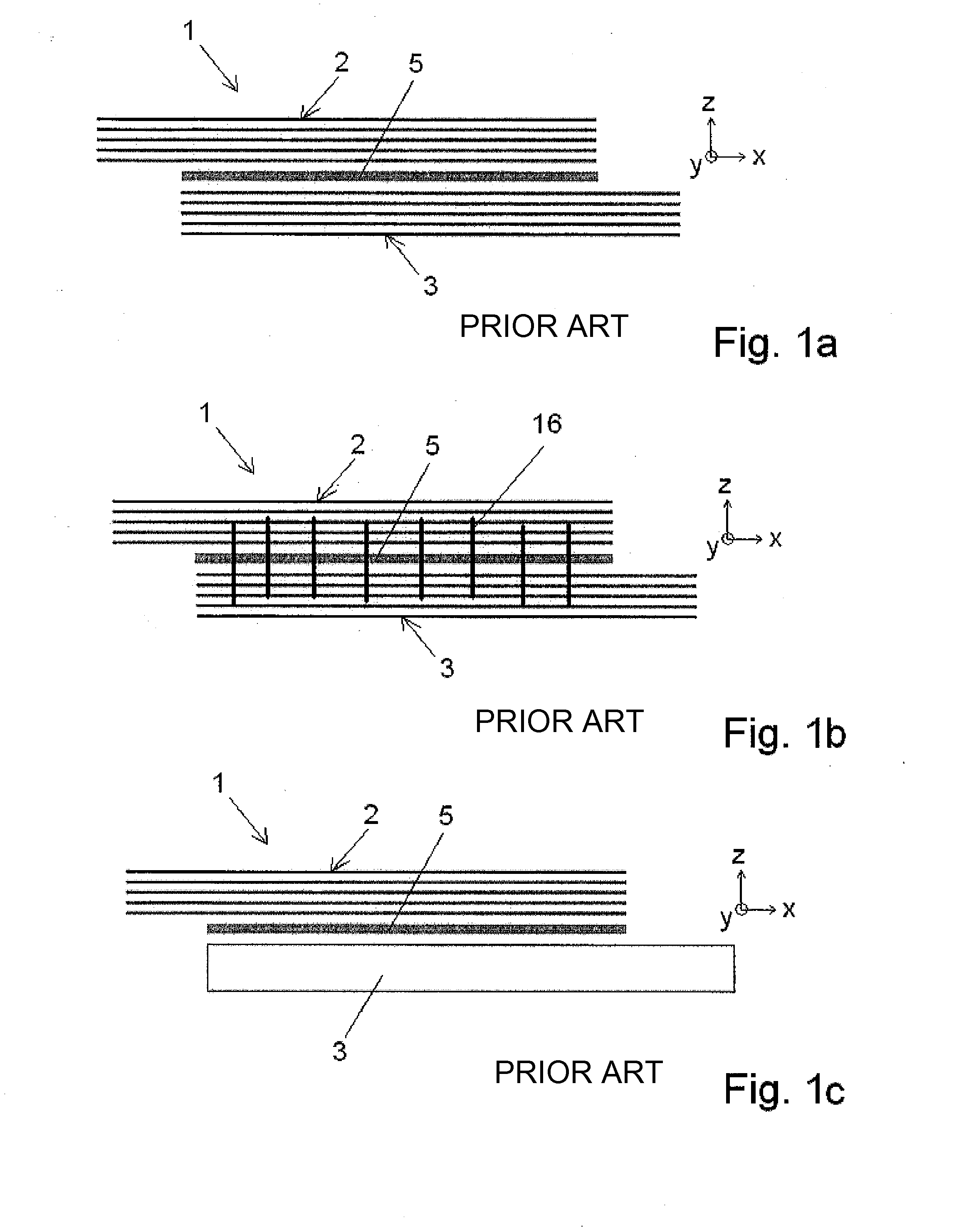
[0055]FIGS. 1a-c have already been explained in the introduction of the description.

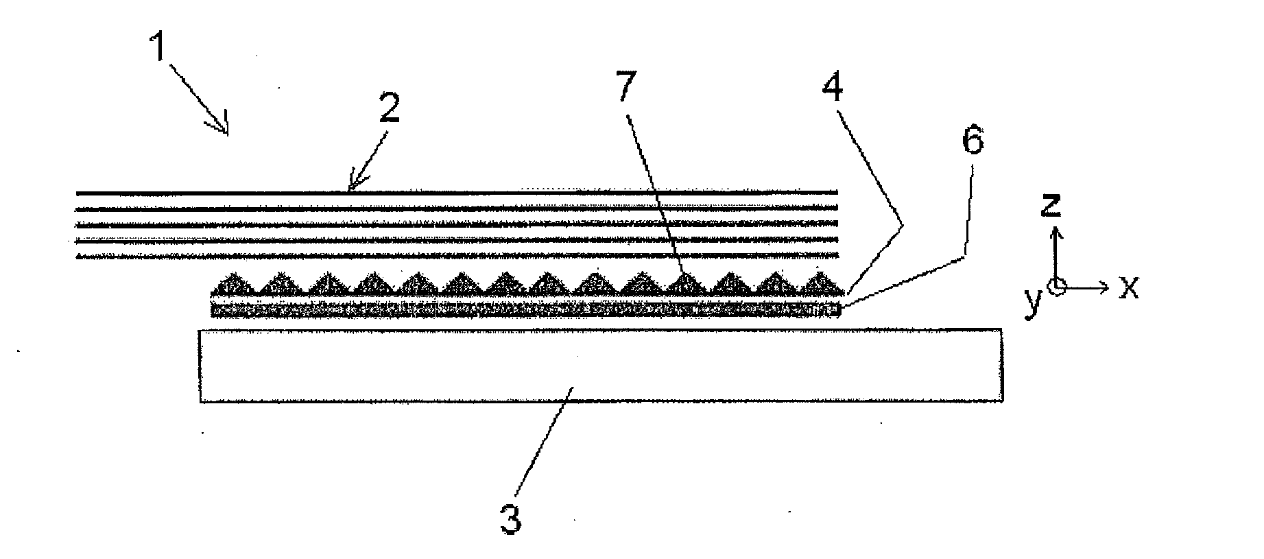
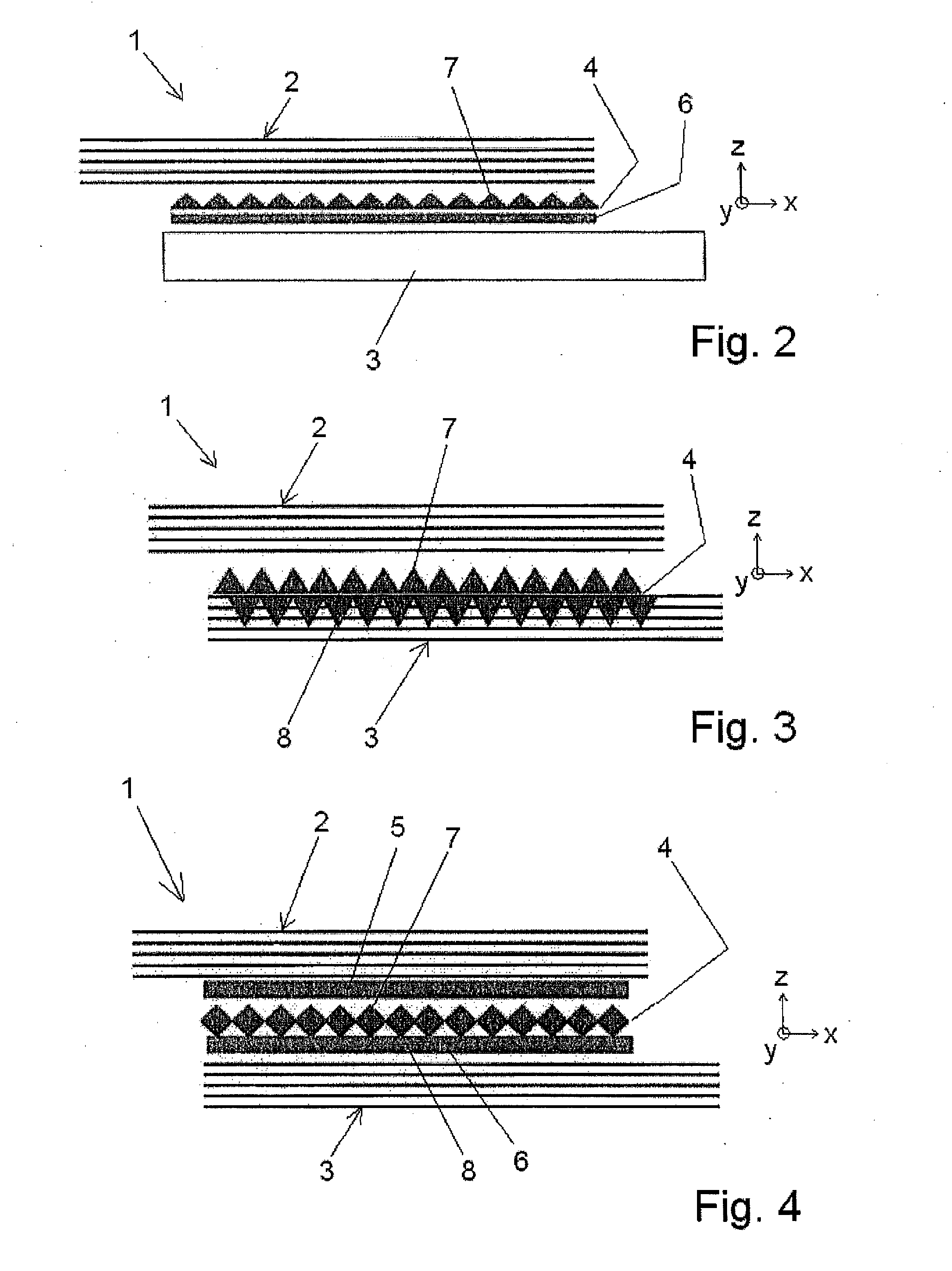
[0056]FIG. 2 shows a schematic sectional view of a first exemplified embodiment for explanation of a method in accordance with the invention for connecting a fibre composite component 2 to a structural component 3. In this case, the fibre composite component can be a prepreg or even a fibre fabric which is impregnated with a matrix.

[0057]A metal foil 4 is formed in such a manner that it acquires an anchoring portion 7 on the side facing the fibre composite component 2. This can be performed e.g. by punch-bending methods, high-speed metal removal, electron beam processing, additive layer manufacturing methods and / or the like. A further description is provided hereinafter in connection with FIGS. 8 to 12. In this example...


PUM

PropertyMeasurementUnit
angleaaaaaaaaaa
weightaaaaaaaaaa
thicknessaaaaaaaaaa

Abstract

In the case of a method for connecting a fibre composite component to a structural component of an aircraft and spacecraft, a metal foil is provided as a transverse reinforcement element between the fibre composite component and the structural component. It is formed with at least one anchoring portion which protrudes from the surface facing the fibre composite component and is inserted between the fibre composite component and the structural component. A corresponding arrangement is produced in accordance with this method.

Description

CROSS-REFERENCE TO RELATED APPLICATIONS[0001]This application is a continuation of and claims priority to PCT / EP2010 / 068802 filed Dec. 3, 2010 which claims the benefit of and priority to U.S. Provisional Application No. 61 / 267,643, filed Dec. 8, 2009 and German patent application No. 10 2009 047 671.7, filed Dec. 8, 2009, the entire disclosure of which are herein incorporated by reference.FIELD OF THE INVENTION[0002]The present invention relates to a method for connecting a fibre composite component to a structural component of an aircraft and spacecraft, and to a corresponding arrangement.BACKGROUND OF THE INVENTION[0003]Although it is applicable to any fibre composite components, the present invention and the problem forming the basis thereof will subsequently be explained in more detail with reference to carbon fibre-reinforced plastics (CFRP) components (also referred to as fibre composite components), e.g. structural components of an aeroplane.[0004]The stiffening of CFRP outer...

Claims


Application Information

Patent Timeline
Patent Type & Authority Applications(United States)
IPC IPC(8): B32B7/08B23P13/00
CPCB29C35/02Y10T29/49622B29C65/3444B29C65/3448B29C65/3476B29C65/364B29C65/5057B29C65/564B29C66/1122B29C66/30341B29C66/43B29C66/742B29K2101/12B29K2105/06B29K2105/24B29K2105/243B29K2105/246B29K2305/00B29K2307/00B29L2031/3076B64C2001/0072F16B15/0023F16B15/0046Y02T50/433B29C65/3644B29C65/3656B29C65/368B23P13/00B32B7/08B29C65/5021B29C66/73921B29C66/72141B29C65/483B29C66/73751B29C66/73752B29C66/73753B29C66/73754Y10T428/24612B29C65/344B29C66/7212B29C66/721B29C66/72143Y02T50/40B29K2307/04
Inventor PACCHIONE, MARCOFURFARI, DOMENICO
Owner AIRBUS OPERATIONS GMBH
Why Eureka
Try Eureka