
Structural members having improved resistance to fatigue crack growth

a structural member and growth rate technology, applied in the direction of non-electric welding apparatus, building components, metal-working apparatus, etc., can solve the problems of increasing the number of fatigue initiation sites, increasing the likelihood of fatigue crack formation, and increasing the number of fatigue crack initiating sites in the stiffening member, so as to improve improve the damage tolerance. , the effect of improving the growth rate of fatigue cracks

Inactive Publication Date: 2005-12-13
ARCONIC INC
View PDF28 Cites 18 Cited by
  • Summary
  • Abstract
  • Description
  • Claims
  • Application Information

AI Technical Summary

Benefits of technology

"The present invention is about improving the damage tolerance of extruded structural members. This is achieved by intentionally increasing the amount of fiber texture in specific areas of the microstructure of the structural member. This helps to reduce the rate of fatigue crack growth and makes the structural member more durable. The invention also includes the use of stiffeners and intra-stiffener areas to further enhance the resistance to fatigue crack growth. Additionally, the invention also includes the use of rolled plates made from the improved structural members, which also have better fatigue crack growth resistance and damage tolerance."

Problems solved by technology

Although one might desire to design lower wings using a higher strength alloy to maximize weight efficiency, the damage tolerance characteristics of such alloys often fall short of design expectations.
Narrower spacings are not typically used in “built-up” stiffened panels because there is a trade-off between the increased performance and the additional assembly and fastener costs associated with attaching additional stringers.
Finally, the addition of more fastener holes also increases the number of fatigue initiation sites increasing the likelihood that a fatigue crack will form.
Likewise, a fatigue crack initiating in the stiffening member can propagate into the web or skin.
The reduced damage tolerance of an integral structure relative to a built-up structure has limited their used on larger aircraft particularly in structure predominantly loaded in tension such as the lower wing panel.
Current alloys for lower wing skin members in commercial jet aircraft all lack in the property needs required for tomorrow's high capacity aircraft.

Method used


Image

  • Structural members having improved resistance to fatigue crack growth
  • Structural members having improved resistance to fatigue crack growth
  • Structural members having improved resistance to fatigue crack growth

Examples


examples

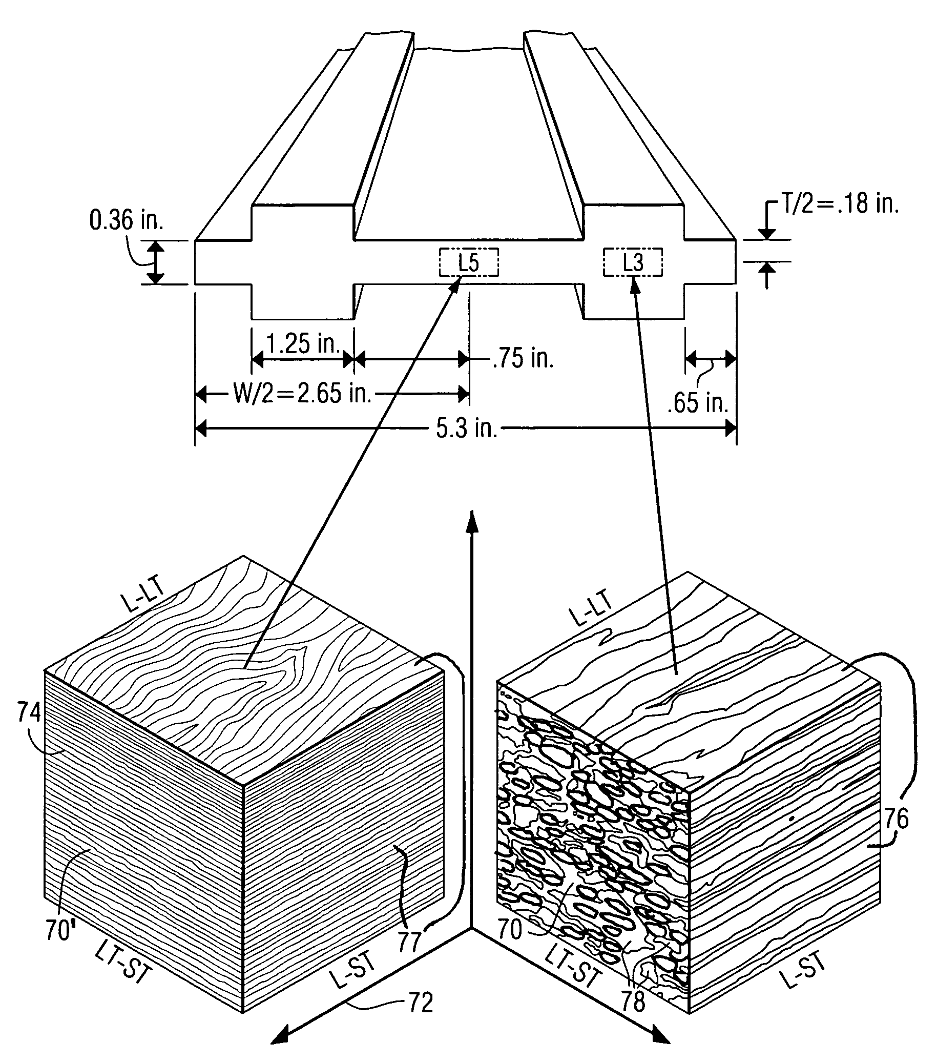
[0081]Integrally stiffened members represented in shapes used in aerospace structures are fabricated by extruding to near net shape. As described in priority document of U.S. Provisional Patent Ser. No. 60 / 339,715, cross-referenced earlier, the variability observed in fatigue crack growth (FCG) tests of damage-tolerant extrusion alloy 2026 in the -T3511 condition was a result of the crystallographic texture that developed during processing. Two extrusion processing parameters were identified as having the most significant influence on texture evolution and subsequent FCG behavior: extrusion aspect ratio (AR) and extrusion ratio.

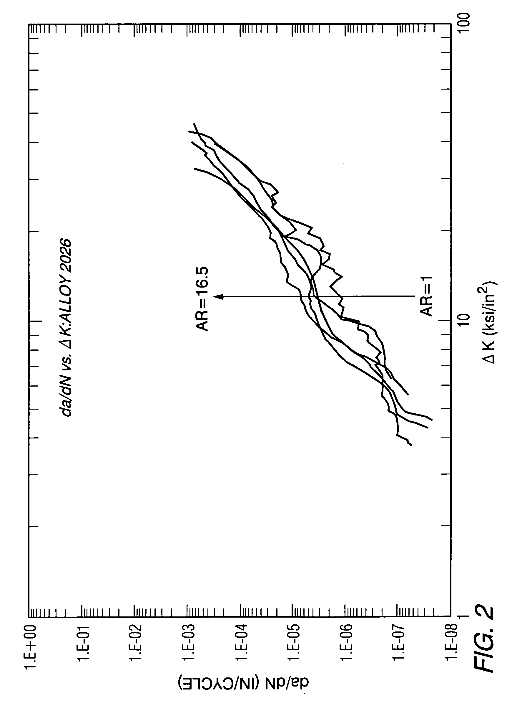
[0082]The observed effect of aspect ratio (AR), extrusion width divided by the thickness on FCG behavior is clearly illustrated in FIG. 2 for Alloy 2026. As the aspect ratio of various samples increases from unity, i.e., an extrusion with a square cross section, to values from 15 to 20, i.e. extrusions with rectangular cross-sections, the resistance to FCG (f...


PUM

PropertyMeasurementUnit
aspect ratioaaaaaaaaaa
temperatureaaaaaaaaaa

Abstract

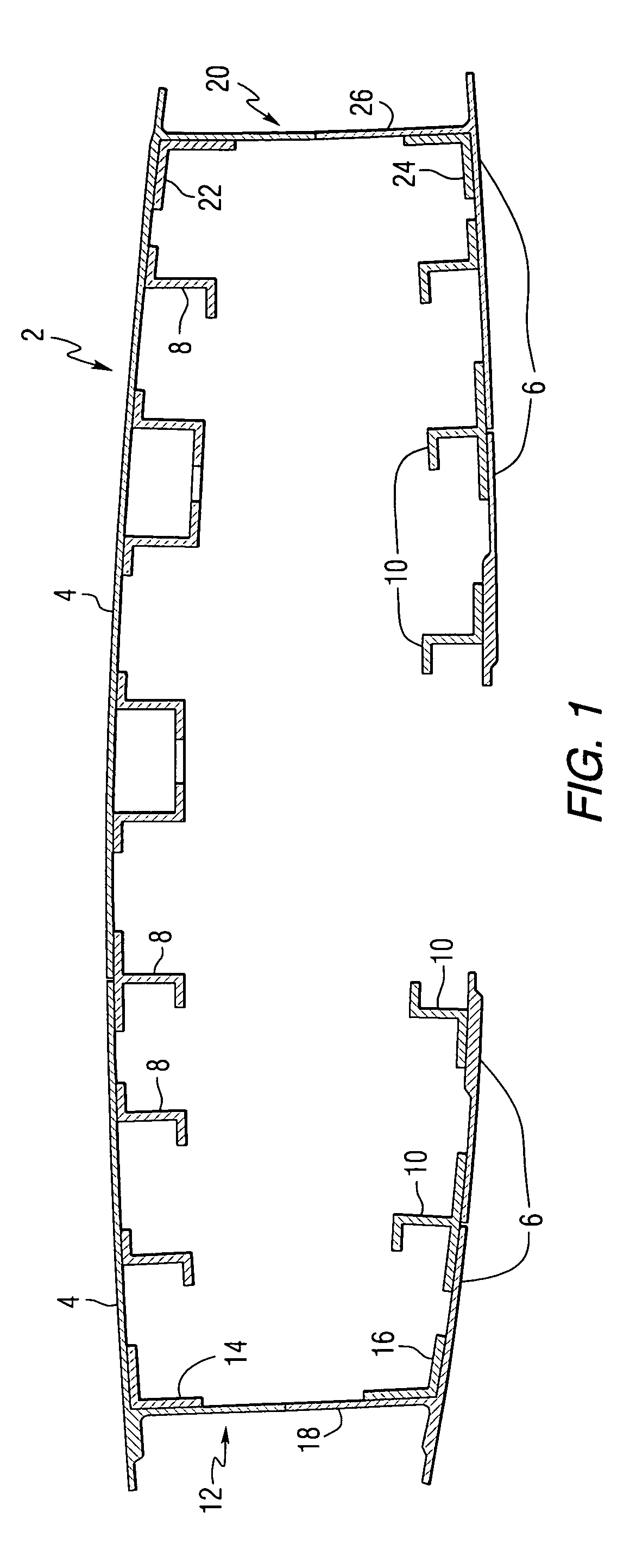
An extruded structural member having improved damage tolerance containing a base section (6); a stiffening section having at least one pair of structural stiffeners (10), the structural stiffeners integral with the base section (6) and projecting outwardly thereof; and at least one intra-stiffener (90) area positioned between the pair of structural stiffeners (10), the intra-stiffener area (90) having a microstructure with intentionally increased amounts of fiber texture to reduce the rate of fatigue crack growth in the extruded structural member.

Description

CROSS REFERENCE TO RELATED APPLICATIONS[0001]This application is a continuation of U.S. patent application Ser. No. 10 / 286,937, filed Nov. 2, 2002 now abandoned, entitled “Structural Members Having Improved Resistance To Fatigue Crack Growth”, which claims the benefit of U.S. Provisional Patent Application Ser. No. 60 / 339,715, filed Nov. 2, 2001, which is incorporated herein in its entirety.FIELD OF THE INVENTION[0002]This invention pertains to damage tolerant aluminum structures made from aluminum alloys and the methods of making such structures.BACKGROUND OF THE INVENTION[0003]As the size of new jet aircraft gets larger, or as current jetliner models grow to accommodate heavier payloads and / or longer flight ranges to improve performance and economy, the demand for weight savings of structural components, such as fuselage, wing and spar parts continues to increase. The aircraft industry is meeting this demand by specifying higher strength, metal parts to enable reduced section thic...

Claims


Application Information

Patent Timeline
Patent Type & Authority Patents(United States)
IPC IPC(8): B21B1/02B21B1/08B21B3/00B21C23/14B64C3/24C22C21/16C22F1/053C22F1/057
CPCB21B1/08B21C23/001B21C23/14C22C21/16C22F1/053C22F1/057B64C3/24B21B1/026B21B2001/022B21B2003/001Y10T428/12389Y10S148/902Y10T428/12375Y10T428/1241
Inventor GARRATT, MATTHEW D.BRAY, GARY H.DENZER, DIANA K.ULYSSE, PATRICK
Owner ARCONIC INC
Learn More