Liquid Power Generation Apparatus and Liquid Power Generation System

a technology of power generation apparatus and power generation system, which is applied in the direction of mechanical equipment, electric generator control, machines/engines, etc., can solve the problems of increasing limited installation place, and small electricity generation capacity to be obtained with respect to an increase in the size of the apparatus

Inactive Publication Date: 2013-06-20
SHINOHARA TOORU
View PDF13 Cites 10 Cited by
  • Summary
  • Abstract
  • Description
  • Claims
  • Application Information

AI Technical Summary

Benefits of technology

[0148]The operation is carried out for 1 minute/process and, in this time period, a time for generating electricity is 45 seconds, a mass body return time is 15 seco

Problems solved by technology

Therefore, an installing place is limited, and an electricity generating capacity to be obtained is small with respect to an increase in size of the apparatus.
In this regard, an increase in size of the apparatus is also encouraged, and an installing place is limited.
Fur

Method used


Image

  • Liquid Power Generation Apparatus and Liquid Power Generation System
  • Liquid Power Generation Apparatus and Liquid Power Generation System
  • Liquid Power Generation Apparatus and Liquid Power Generation System

Examples


third embodiment

of Liquid Power Generation Apparatus

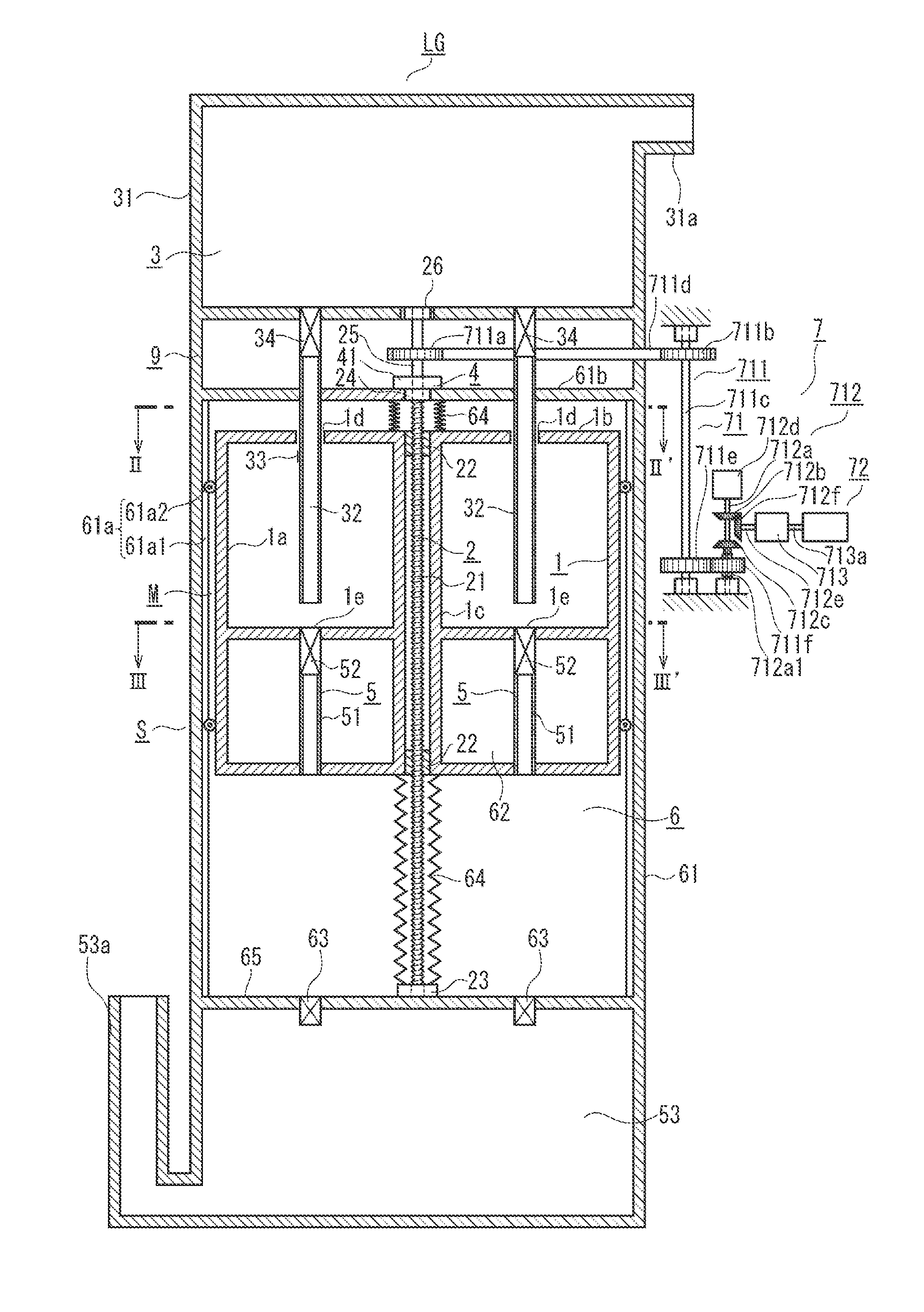
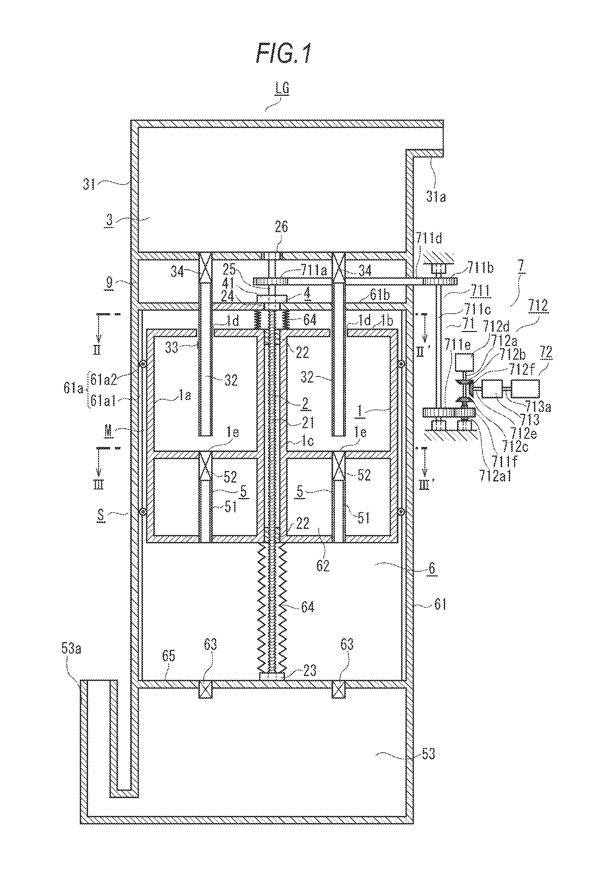
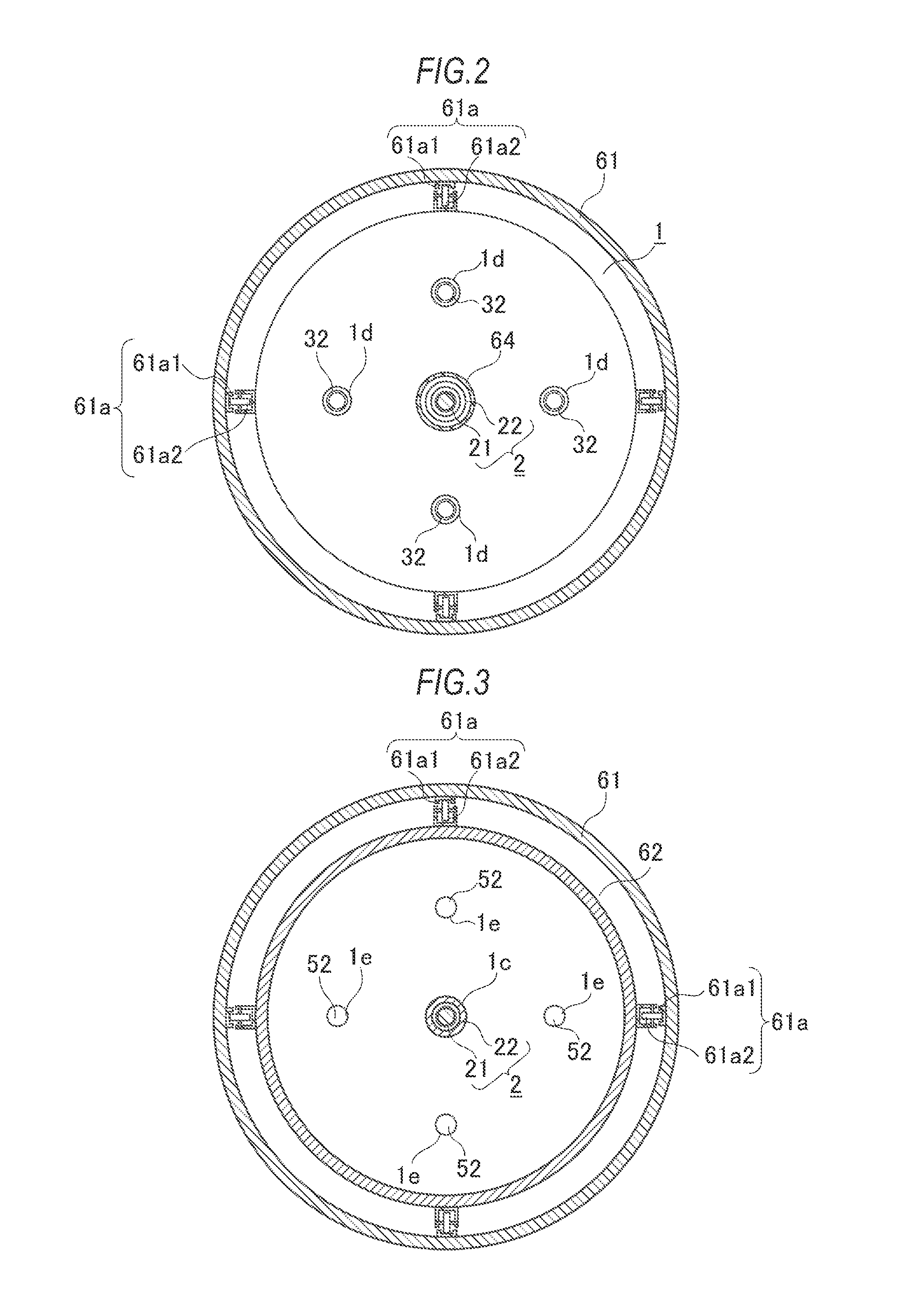
[0122]A third embodiment of a liquid power generation apparatus LG according to the present invention will now be described with reference to FIG. 6. It is to be noted that like reference numerals denote parts equal to those in FIG. 1 to FIG. 4, and a description thereof will be omitted. In the drawing, in this embodiment, a pair of liquid power generation apparatuses LG are arranged on left and right sides of the drawing. However, a mutual relationship between the pair of liquid power generation apparatuses LG will be described later since the second embodiment of a later-described liquid power generation system will be configured. This embodiment relates to a configuration of the single liquid crystal power generation apparatus LG.

[0123]In this embodiment, a float 62 is arranged at a position that is separated downward from a bottom portion of a movable liquid tank 1. Therefore, a discharge tube 51 can be elongated in the vertical direction. It ...

fourth embodiment

of Liquid Power Generation Apparatus

[0128]A configuration of a fourth embodiment of a liquid power generation apparatus LG according to the present invention will now be described with reference to FIG. 7 to FIG. 10. It is to be noted that like reference numerals denote parts equal to those in FIG. 6, and a description thereof will be omitted. This embodiment solves the problems of the present invention described above and facilitates introducing a liquid into a movable liquid tank 1 to secure a desired mass, generating electricity, and then returning the movable liquid tank 1 to its original upper position using the liquid discharged to the inside of an outer tank 61 like the third embodiment, but it is different from the third embodiment in that the movable liquid tank 1 can be easily moved to a desired position even though an amount of the liquid to be discharged is relatively small.

[0129]Meanwhile, in the previous third embodiment, an inside diameter of the outer tank 61 is fixe...

example 1

Specification Example 1 of Liquid Power Generation Apparatus LG

[0147]A cylindrical shape, a maximum diameter: 1.5 m, a height: 4.2 m,

The liquid feed tank 31, a discoid shape, a diameter: 1.5 m, a height: 0.35 m

A generator mechanism portion, a mass: 1000 kg, a diameter: 1.5 m, a height: 2.5 m

The movable liquid tank 1 (internal volume), a diameter: 1.4 m, a height: 2.5 m (a water filling amount: 600 kg)

The float 62 (internal volume), a diameter: 0.76 m, a height: 1.0 m (buoyancy force: −450 kg), return effective buoyancy force: −50 kg

A movable mass body's own weight (including a drainage tube, a weight, and others): −400 kg

A ball spring effective length D: 1.0 m

The outer tank 61

The movable water tank surrounding portion 68, a cylindrical shape, a diameter: 1.5 m, a height: 1.4 m

The float surrounding portion 67, a cylindrical shape, a diameter: 0.87 m, a height: 2.1 m

The drainage tank 53, a discoid shape, a diameter: 1.5 m, a height: 0.35 m

A used amount of water: 0.6 m3 / minute (introdu...


PUM


Abstract

A liquid power generation apparatus comprises a movable liquid tank, a linear-rotation conversion mechanism, liquid introducing means, controlling means, liquid discharging means, liquid tank returning means, and a generator. The movable liquid tank can vertically move. The linear-rotation conversion mechanism comprises a male screw shaft and a female screw body and generates a rotation output in tandem with the vertical movement of the movable liquid tank. The liquid introducing means introduces a liquid when the movable liquid tank is provided at an upper position. The controlling means moves down the movable liquid tank having the liquid therein from the upper position. The liquid discharging means discharges the liquid when the movable liquid tank is lowered. The liquid tank returning means moves up the lowered movable liquid tank and returns it to its original position. The generator generates electricity by using a rotation output from the linear-rotation conversion mechanism.

Description

BACKGROUND OF THE INVENTION[0001]1. Field of the Invention[0002]The present invention relates to a liquid power generation apparatus that utilizes a liquid such as water and generates electricity and to a liquid power generation system using this apparatus.[0003]2. Description of the Related Art[0004]A water receiving tank is connected to a balancer through a belt, an intermediate portion of the belt is hoisted by a pulley, and the pulley is disposed to a rotary shaft of a generator. Further, when the water receiving tank is placed at an upper position, water is injected from the water tank through a volume regulating faucet. As a result, a weight of the water receiving tank exceeds that of the balancer, the water receiving tank is heavier than the balancer, and hence the water receiving tank is moved down. When the water receiving tank reaches the ground, a projection provided on a lower surface of a lid constituting a bottom of the water receiving tank is pushed upward. As a resul...

Claims


Application Information

Patent Timeline
IPC IPC(8): H02K57/00
CPCH02K57/003Y02E10/20Y02E60/17F03B17/025Y02E10/28F03B17/005F03G7/08Y02E60/16F03B13/06F03B17/00
Inventor SHINOHARA, TOORU
Owner SHINOHARA TOORU
Why Eureka
Try Eureka