High efficiency magnetic core electrical machines

a high-efficiency, electrical machine technology, applied in the direction of magnetic circuit rotating parts, magnetic circuit shape/form/construction, propulsion systems, etc., can solve the problems of increasing fossil fuel costs, increasing the cost of fossil fuels, and the inability to meet the needs of high-efficiency electrical machines, so as to improve energy utilization and/or power generation efficiency.

Inactive Publication Date: 2013-06-20
SULLIVAN JOHN T
View PDF4 Cites 73 Cited by
  • Summary
  • Abstract
  • Description
  • Claims
  • Application Information

AI Technical Summary

Benefits of technology

[0014]It is accordingly an objective of the invention to provide electrical machines that may economically be applied to a variety of applications to improve energy utilization and / or power generation efficiency.
[0017]The first set of high efficiency magnetic core electrical machines utilize, in accordance with the principles of a first preferred embodiment of the invention, three-dimensionally converging circumferential, axial, and radial flux paths to increase the flux density through individual stator coils. The axial and radial flux paths are provided by circumferentially extending arms of three dimensional pole structures that may be assembled to form discrete rings, the pole structures further including arms that extend transversely to the rings in both radial and vertical directions to thereby provide flux paths that converge from three different dimensions. The three dimensional poles structures may include coupling structures, such as mortise and tenon arrangements, for easy assembly and to increase the surface area of the interface between the pole structures.
[0018]A second set of high efficiency magnetic core electrical machines utilizes, in accordance with the principles of a second preferred embodiment of the invention, auxiliary movable permanent magnet structures situated in the flux return paths of pole structures that may otherwise be conventional. The permanent magnet structures are freely movable relative to the pole structures to follow changes in the flux passing through the pole structures, for example by rotating, to provide a boost effect that increases the flux density in the return path.

Problems solved by technology

The need for high efficiency electrical machines has become increasingly critical as fossil fuel supplies become depleted and / or more expensive to extract.
Despite the increasing cost of fossil fuels, however, motors and generators that utilize electro-magnetic induction continue to be less cost effective in many applications than fossil fuel based motors and generators, particularly for transportation and alternative power generation.
However, rare-earth materials such as samarium and neodymium, which are respectively combined with cobalt and iron / boron to form high strength permanent magnets, are currently available from only a few sources, resulting in limited supply and high prices.
However, the flux paths between the permanent magnets and through the poles of the conventional magnetic core electrical machines are two dimensional, which limits the amount of flux in the return paths.

Method used


Image

  • High efficiency magnetic core electrical machines
  • High efficiency magnetic core electrical machines
  • High efficiency magnetic core electrical machines

Examples


Embodiment Construction

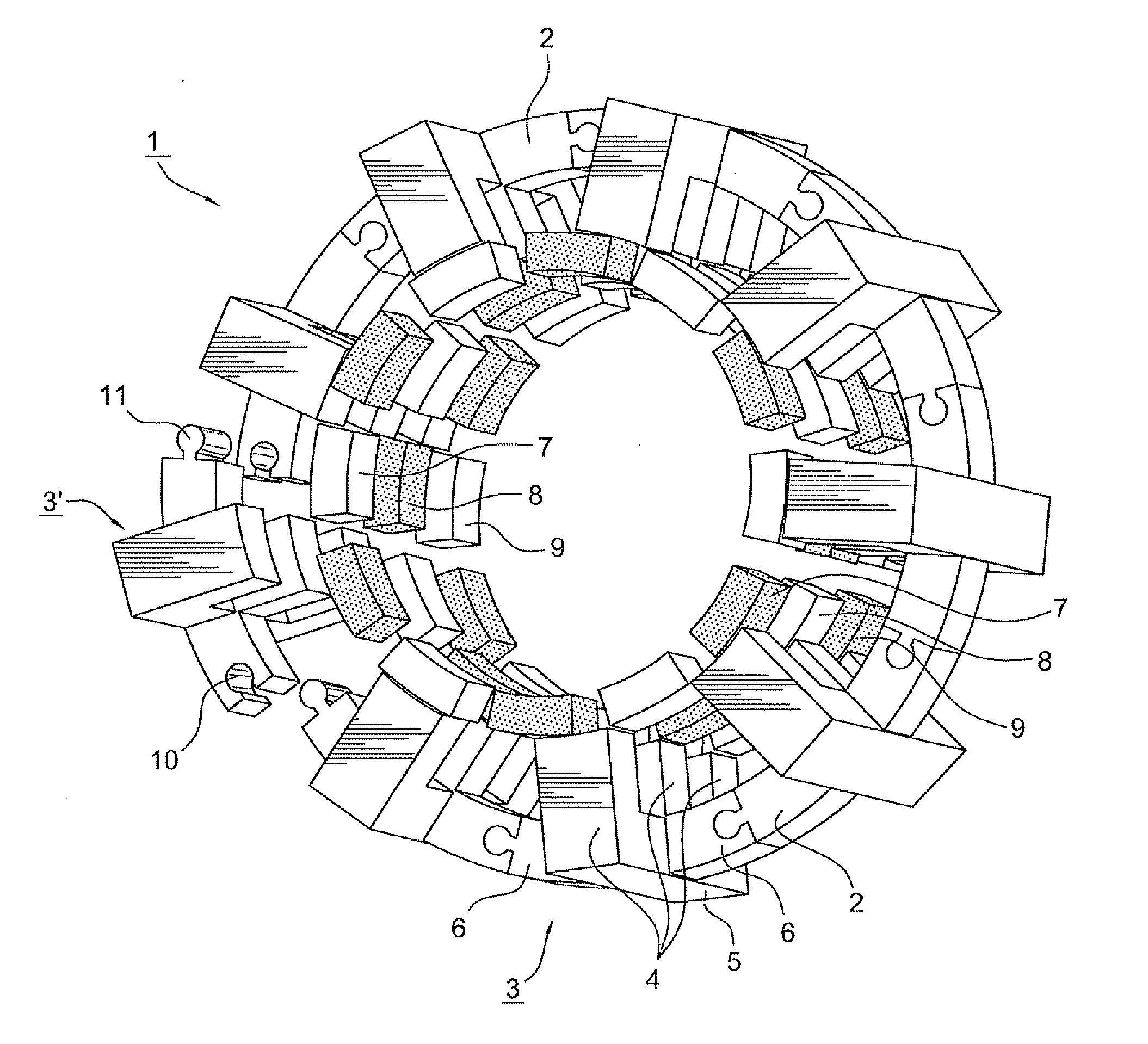
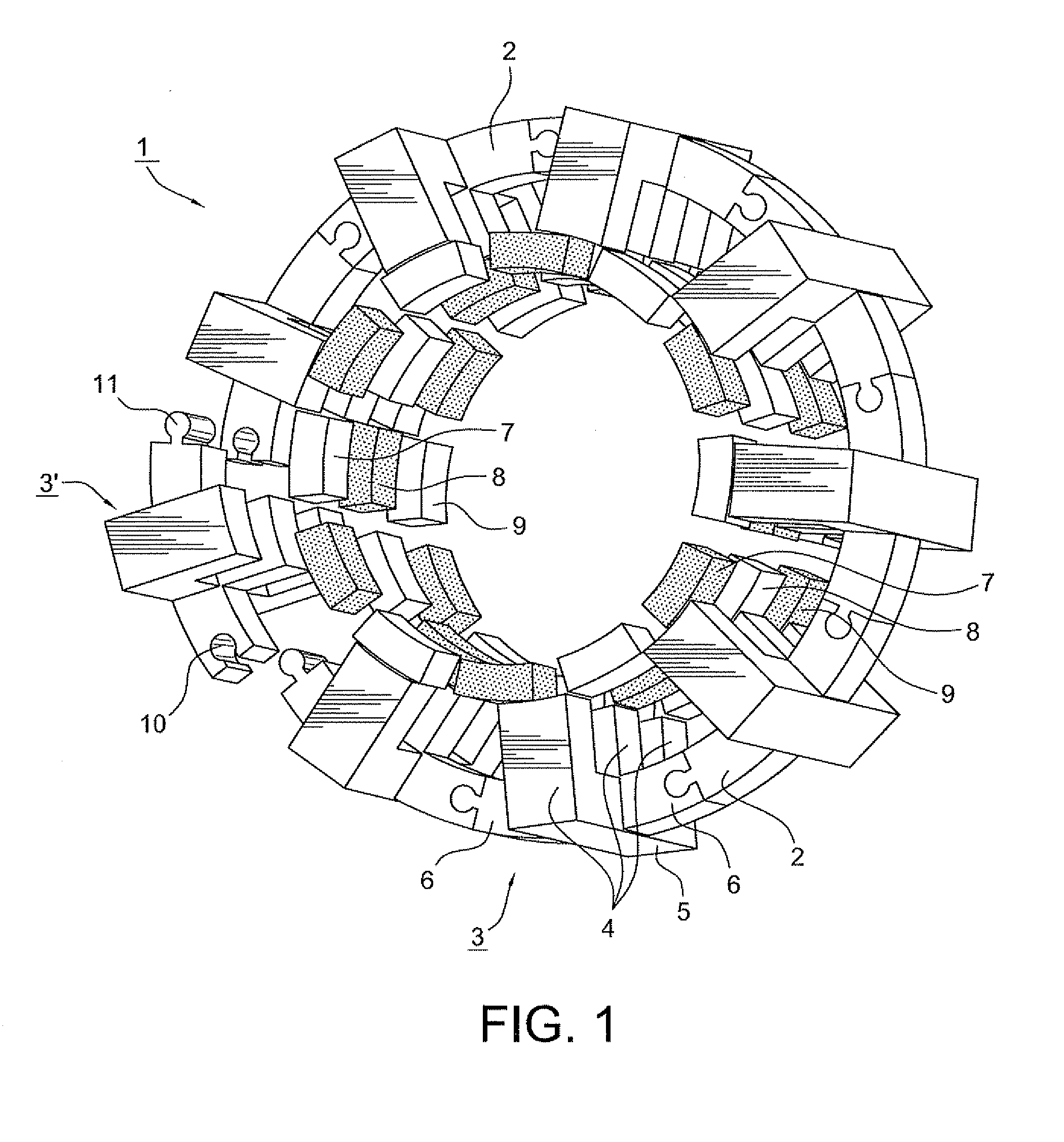
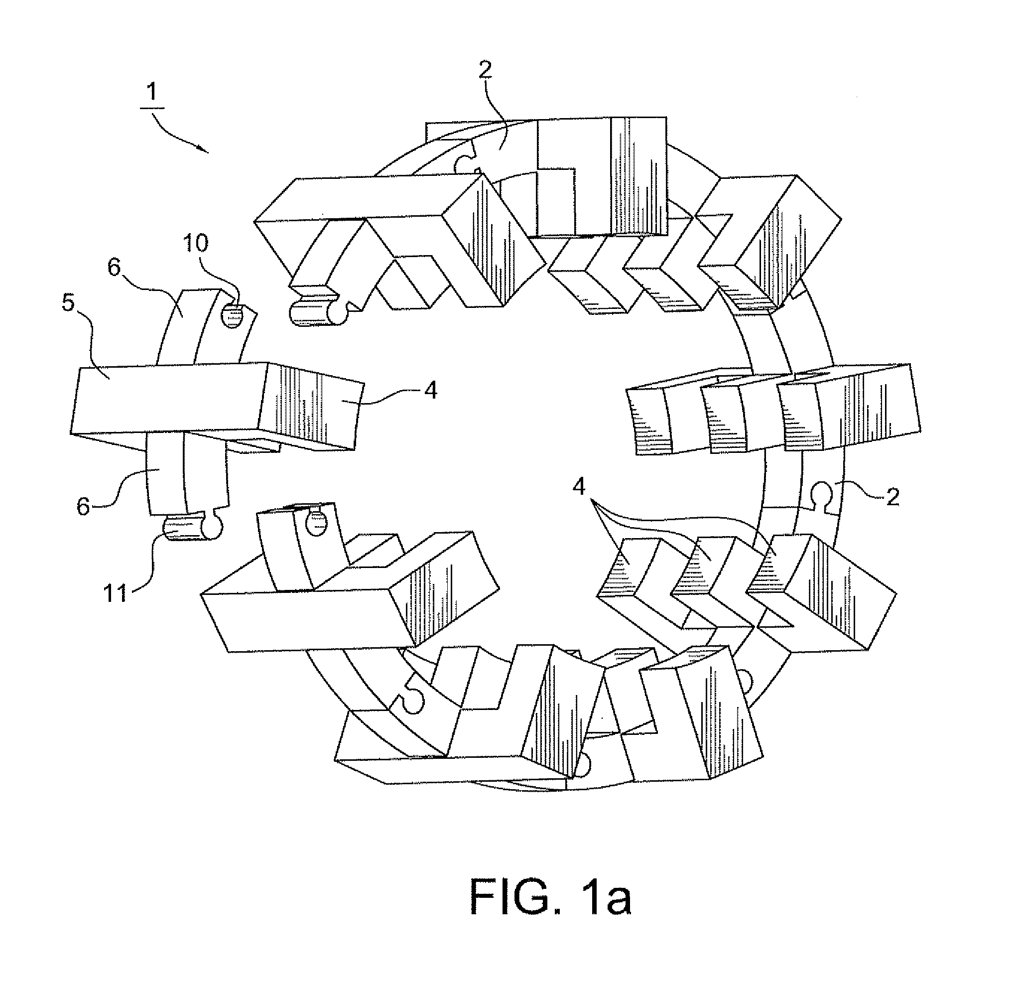
[0110]As illustrated in FIGS. 1, 1a, and 1b a stator 1 is arranged to provide three-dimensionally converging axial, radial, and circumferential flux paths, and includes at least one annular flux return ring 2 that include a plurality of individual pole structure modules or units 3, each including three radially extending pole arms 4, a vertical connecting arm 5 that together with the pole arms 4 forms an “E” or comb shape, and circumferentially extending arc shaped connecting extensions 6. The ends of pole arms 4 face, and magnetically interact with, respective upper, middle, and lower permanent magnets 7-9, which are supported by a rotor structure 12 (shown in FIG. 1b). The individual pole structure modules or units 3 are joined at the connecting extensions 6 by connection structures that may take the form of mortises 10 and tenons 11. One of the pole structure modules or units 3, indicated by the label 3′, is illustrated as being detached from the other modules or units. Reference...


PUM


Abstract

A high efficiency magnetic core electrical machine includes magnet and coil assemblies that may be axially stacked to form modules. The magnet sub-assemblies include magnet locators on which multiple permanent magnets are arranged, and the coil sub-assembly includes a pair of bobbin holders supporting multiple bobbins and magnetic cores that extend through the bobbins and through openings in the bobbin holders to form magnetic poles that face the permanent magnets. The permanent magnets and magnetic poles may be arranged in various zero-cogging configurations, including one in which the permanent magnets on opposite sides of the coil assembly are skewed relative to each other to cause cogging force cancellation. In addition, a power matching circuit may be used to optimize the output power of the electrical machine to rotor speed when the electrical machine is used as a generator.

Description

BACKGROUND OF THE INVENTION[0001]1. Field of the Invention[0002]This invention relates to electrical machines that utilize permanent magnets / electrical coil interactions to generate torque (in the case of a motor) or electricity (in the case of a generator), and in particular to pole structures and flux return paths having a high flux density and / or switching rate so as to improve the efficiency by which the magnetic fluxes interact with the windings to generate currents or torque.[0003]While a wide variety of magnetic core configurations are disclosed, they can be grouped into three general embodiments, each having a number of variations. The first embodiment utilizes three-dimensionally converging axial, radial, and circumferential flux paths to increase the flux density through individual windings. The second embodiment utilizes rotating auxiliary permanent magnet cylinders to respond to, in effect, enhance or amplify flux reversals. The third set of high efficiency flux return c...

Claims


Application Information

Patent Timeline
Patent Type & Authority Applications(United States)
IPC IPC(8): H02K23/40H02K1/06H02K23/36H02K11/00H02K1/18H02K9/00H02K23/60H02K41/03
CPCH02K21/00H02K21/028H02K21/12H02K21/14H02K21/22H02K21/24H02K2201/06H02K41/031H02K1/14H02K1/141H02K1/145H02K1/148H02K3/522H02K21/44
Inventor SULLIVAN, JOHN T.
Owner SULLIVAN JOHN T
Why Eureka
Try Eureka