Amplifier and filter having variable gain and cutoff frequency controlled logarithmically according to digital code

a filter and logarithm technology, applied in gain control, digital/coded signal control, frequency selective two-port network, etc., can solve the problems of non linearity, uncontrollable sections, and affecting the efficiency of the amplifier, so as to achieve the effect of easy setting a variable gain

Active Publication Date: 2013-06-20
SAMSUNG ELECTRONICS CO LTD
View PDF1 Cites 15 Cited by
  • Summary
  • Abstract
  • Description
  • Claims
  • Application Information

AI Technical Summary

Benefits of technology

[0020]Aspects of the present invention are to address at least the above-mentioned problems and / or disadvantages and to provide at least the advantages described below. Accordingly, an aspect of the present invention is to provide a variable resistance circuit for easily setting a variable gain using a digital control code, and a variable gain amplifier circuit.

Problems solved by technology

However, such non linearity degrades efficiency.
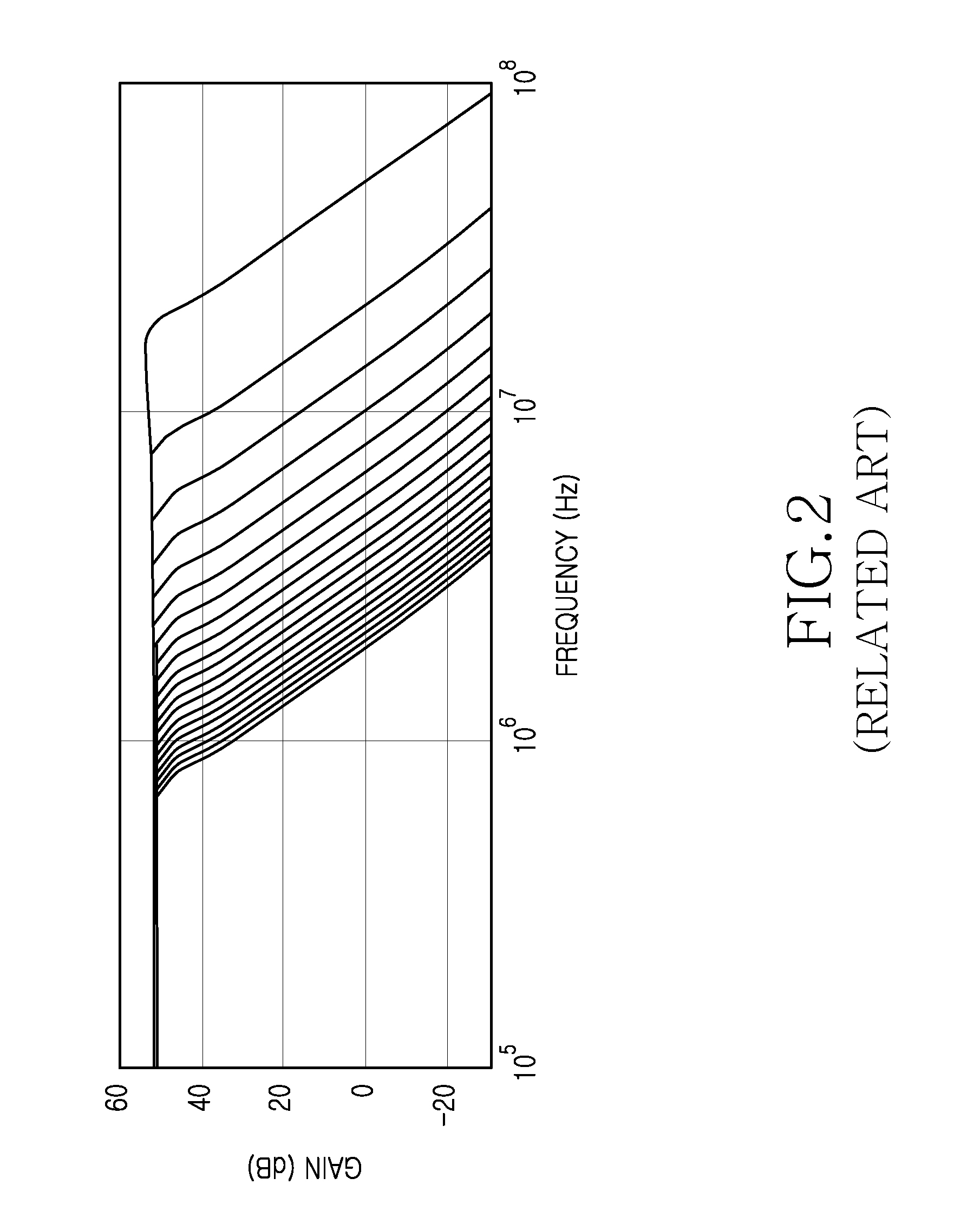
This degrades not only the efficiency but also the accuracy of the variable resistance in a high frequency band as shown in FIG. 2, and thus results in uncontrollable sections.
As a result, an uncontrollable section of the cutoff frequency is generated.
Referring to FIG. 3, because it is not easy to set the cutoff frequency and the gain using the dB, a complicated digital logic circuit is required to logarithmically convert the linear digital code if necessary.
Since the approximate value is subject to considerable error, the implementation increases the number of bits from 2 bits to 4 bits.
However, when the cutoff frequency and the gain are converted at the same time, the combination increases geometrically and it is not easy to realize the method with a simple equation.

Method used


Image

  • Amplifier and filter having variable gain and cutoff frequency controlled logarithmically according to digital code
  • Amplifier and filter having variable gain and cutoff frequency controlled logarithmically according to digital code
  • Amplifier and filter having variable gain and cutoff frequency controlled logarithmically according to digital code

Examples


Embodiment Construction

[0038]The following description with reference to the accompanying drawings is provided to assist in a comprehensive understanding of exemplary embodiments of the invention as defined by the claims and their equivalents. It includes various specific details to assist in that understanding but these are to be regarded as merely exemplary. Accordingly, those of ordinary skill in the art will recognize that various changes and modifications of the embodiments described herein can be made without departing from the scope and spirit of the invention. In addition, descriptions of well-known functions and constructions may be omitted for clarity and conciseness.

[0039]The terms and words used in the following description and claims are not limited to the bibliographical meanings, but, are merely used by the inventor to enable a clear and consistent understanding of the invention. Accordingly, it should be apparent to those skilled in the art that the following description of exemplary embod...


PUM


Abstract

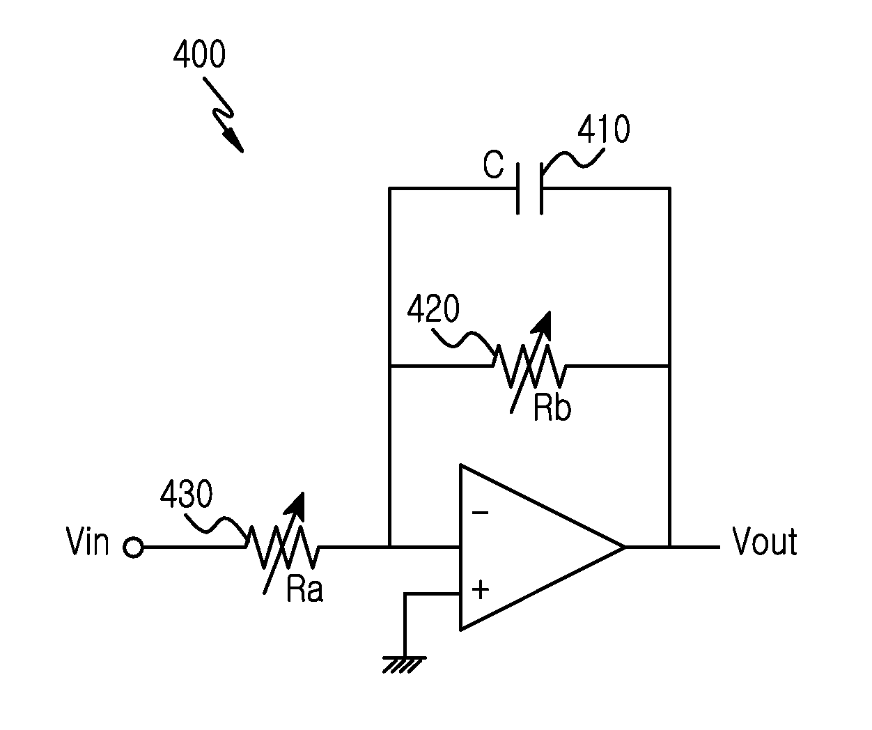
A variable gain amplifier circuit is provided. The circuit includes an operational amplifier for amplifying and outputting an input signal according to a cutoff frequency and a gain, a feedback resistor for changing a first resistance according to a first digital control code value which determines the cutoff frequency, and an input resistor for changing a second resistance according to a second digital control code value which is determined based on a difference of the first digital control code value and a gain code value. The gain is determined by a ratio of the first resistance and the second resistance and linearly changes on a decibel (dB) basis according to the first digital control code value, the cutoff frequency is inversely proportional to the first resistance and linearly changes on a log scale, and the variable gain can be easily set using the control code.

Description

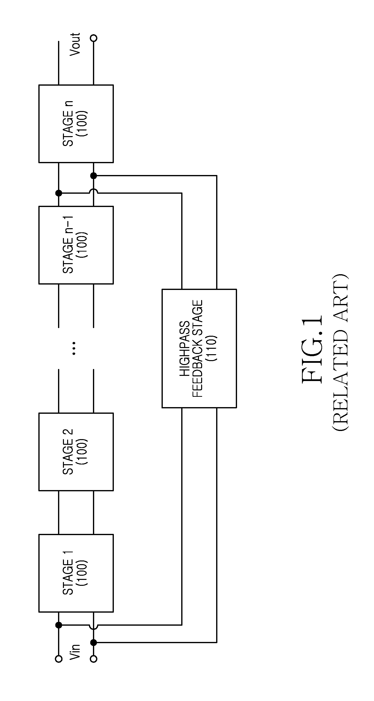
PRIORITY[0001]The present application claims the benefit under 35 U.S.C. §119(a) of a Korean patent application filed on Dec. 16, 2011 in the Korean Intellectual Property Office and assigned Serial No. 10-2011-0136712, the entire disclosure of which is hereby incorporated by reference.BACKGROUND OF THE INVENTION[0002]1. Field of the Invention[0003]The present invention relates to an analog amplifier and an analog filter for amplifying an analog signal. More particularly, the present invention relates to an amplifier and a filter for logarithmically controlling a variable gain and a cutoff frequency according to a digital control code.[0004]2. Description of the Related Art[0005]FIG. 1 depicts an analog filter structure according to the related art.[0006]Referring to FIG. 1, the analog filter is constructed by coupling a plurality of first or higher order filter stages 100 (e.g., Stage 1, Stage 2, . . . , Stage n). A highpass feedback stage 110 is coupled between a first amplifier st...

Claims


Application Information

Patent Timeline
Patent Type & Authority Applications(United States)
IPC IPC(8): H03G3/00
CPCH03G3/002H03G3/001H03G1/0088H03F3/45475H03F2203/45512H03F2203/45522H03G9/20H03H11/1291H03G3/20H03H11/12
Inventor LEE, JONG-WOO
Owner SAMSUNG ELECTRONICS CO LTD
Why Eureka
Try Eureka