Use of multi-faceted impingement openings for increasing heat transfer characteristics on gas turbine components

a technology of gas turbine components and impingement openings, which is applied in the direction of machines/engines, stators, liquid fuel engines, etc., can solve the problems of reducing fluid velocity, reducing fluid velocity, and reducing fluid flow, so as to reduce cross flow effects, increase heat transfer, and increase cooling fluid velocity

Inactive Publication Date: 2013-06-20
GENERAL ELECTRIC CO
View PDF14 Cites 22 Cited by
  • Summary
  • Abstract
  • Description
  • Claims
  • Application Information

AI Technical Summary

Benefits of technology

[0013]As discussed below, the non-round openings in the impingement cooling sleeves described herein provide much more efficient mixing and heat transfer potential as compared to round openings. That is, it has now been found that the non-round impingement openings increase the cooling fluid velocity and minimize cross flow effects, thereby increasing heat transfer between the cooling fluid and vane surface. The new geometric patterns also generate a vortex field in and around the impingement openings which provide for more efficient mixing and improved air velocity distribution at each opening. This characteristic of the discreet fluid pathways emanating from the center of each opening (e.g., openings having a star-like configuration) significantly improve the heat transfer capabilities of existing nozzle designs due to improved mixing and higher velocity characteristics of the openings.
[0014]In addition, the use of the new impingement openings...

Problems solved by technology

Even though steam has a higher heat capacity than air at nominal operating temperatures, steam cooling designs for turbine vanes and other engine components exhibit certain thermodynamic inefficiencies.
As a result, some components in the hot gas path cannot be cooled as efficiently with steam inside a closed circuit because, for example, the relatively thin structure of the trailing edges of the nozzle vanes precludes effective steam cooling of certain portions of the vanes.
Although relatively high levels of heat transfer can be achieved in a first stage nozzle using impingement cooling with round openings, once the impingement contact occurs, the fluid molecules tend to move para...

Method used


Image

  • Use of multi-faceted impingement openings for increasing heat transfer characteristics on gas turbine components
  • Use of multi-faceted impingement openings for increasing heat transfer characteristics on gas turbine components
  • Use of multi-faceted impingement openings for increasing heat transfer characteristics on gas turbine components

Examples


Embodiment Construction

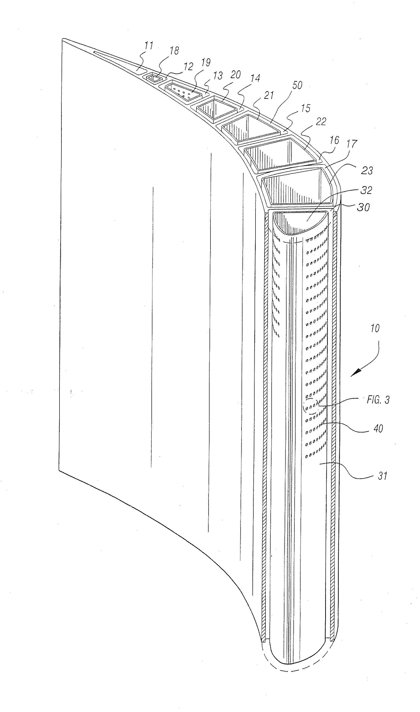
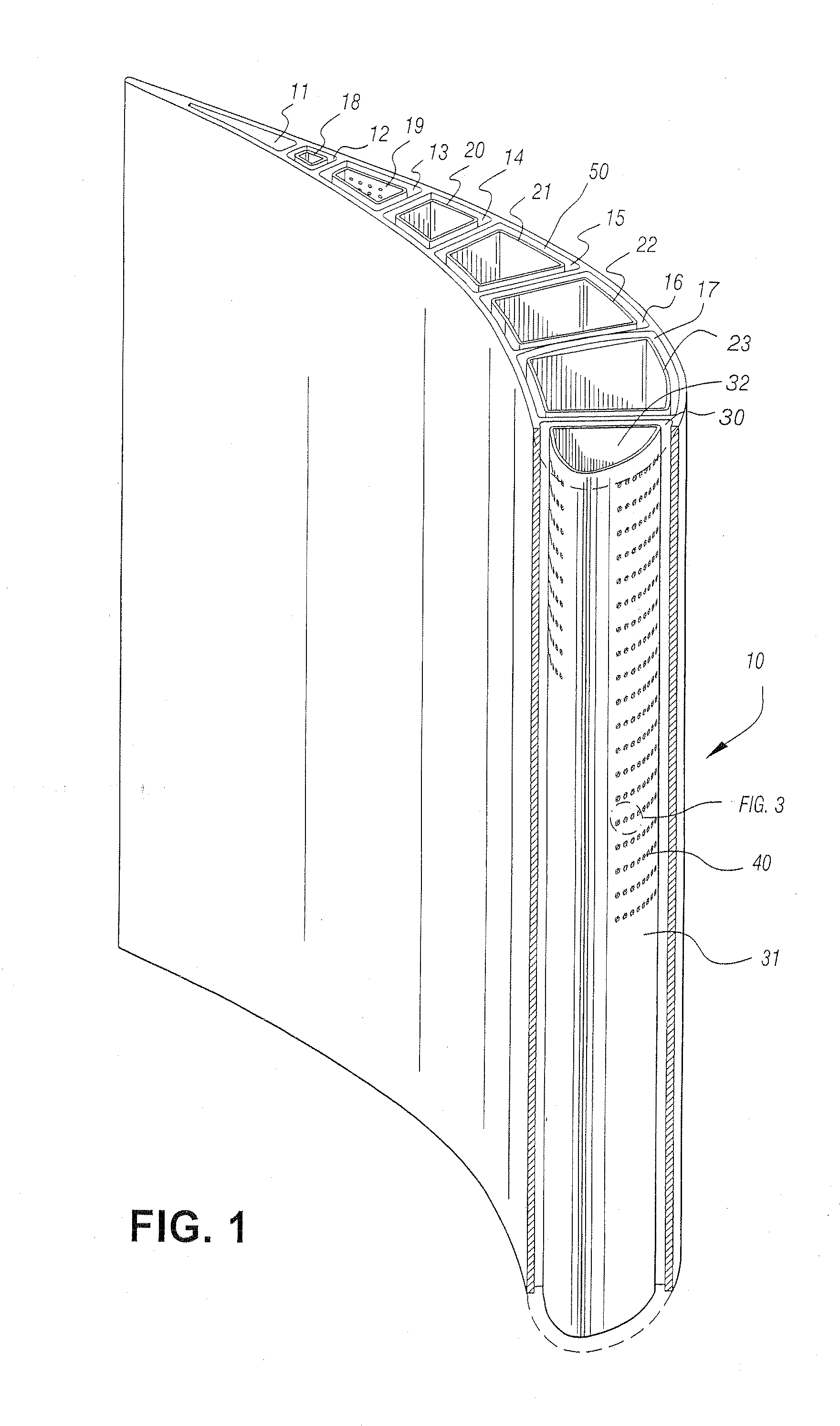
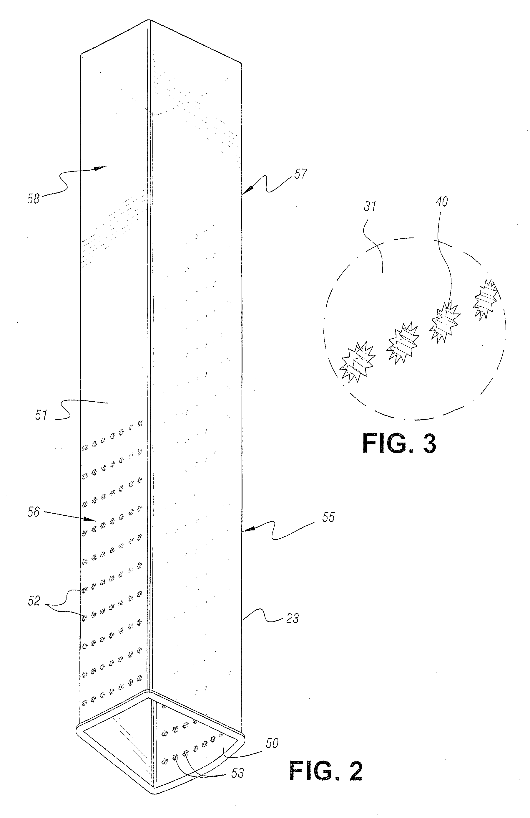
[0021]As noted above, the impingement openings according to the invention improve heat transfer and increase the effective use of cooling air and / or steam to reduce nozzle and other engine component temperatures. The multiple geometric edges that define an opening have a size and configuration that result in a higher impingement jet velocity and increased heat transfer as compared to round openings with a comparable cross sectional area. The use of such multi-faceted impingement holes allows for greater throughput and a net reduction in metal temperatures. It has also been found that the star-like configuration has the capability to develop a vortex flow field that provides for a more efficient mixing of the cooling air before it impacts the vane. The more efficient mixing allows for a higher velocity distribution of the cooling air, and hence higher heat transfer between the fluid and the surface.

[0022]The general form of an exemplary insert sleeve is illustrated in FIGS. 1-3. FIG....


PUM


Abstract

An improved nozzle vane for a gas turbine engine, comprising a vane wall having inner and outer wall surfaces, the wall surfaces being spaced from one another to define a plurality of fluid passageways for a cooling medium; discreet cavities formed by interior wall members disposed between the inner and outer wall surfaces and within the fluid passageway for the cooling medium; a plurality of impingement cooling sleeves disposed in the discreet cavities defined by the inner and outer wall surfaces and by interior wall members; and a plurality of non-round, e.g., serrated, openings in each of the impingement cooling sleeves, with the openings being sufficient in size and number to accommodate the flow of a cooling media.

Description

[0001]The present invention relates to gas turbine engines such as those used for electrical power generation and aircraft engines and, more particularly, to a system for cooling nozzles and associated vanes using a nozzle cavity and vane design with improved convection and impingement cooling capabilities. The invention can also be used for other engine components, such as shrouds, buckets, combustors, as well as with different airfoils and the inner and outer nozzle sidewalls.BACKGROUND OF THE INVENTION[0002]Over the years, various cooling mechanisms have been employed to protect hot gas path components of gas turbine engines during extended operation, particularly stage one nozzles which often encounter the highest temperature exhaust gases. Most closed circuit cooling systems include a plurality of nozzle vane segments extending between inner and outer side walls of the nozzle. Typically, the vanes include cavities in fluid communication with compartments in the outer and inner ...

Claims


Application Information

Patent Timeline
IPC IPC(8): F01D9/06
CPCF05D2250/131F01D5/189Y02T50/676F01D9/065F05D2260/201F01D9/041Y02T50/60
Inventor MALDONADO, JAIME JAVIER
Owner GENERAL ELECTRIC CO
Why Eureka
Try Eureka