
Blade for a turbo machine

Inactive Publication Date: 2013-06-20
SIEMENS AG
View PDF10 Cites 16 Cited by
  • Summary
  • Abstract
  • Description
  • Claims
  • Application Information

AI Technical Summary

Benefits of technology

The invention aims to improve the blades used in turbo machines and enhance the cooling of certain parts to increase their service life. Specifically, the cooling of the extreme edge regions of the platform of adjacent nozzle guide vanes is being improved to achieve these goals.

Problems solved by technology

These blades have to withstand high temperatures and high mechanical forces due to the rotation of the turbine rotor.
Problems arise with extreme front or rear edges of platform regions of the nozzle guide vanes.
The problem is that these regions are subject to hot gas temperatures but are difficult to cool.
However, the jets produced by such arrangements are not able to reach the extreme edge of the platform due to mechanical and seal features at these locations.

Method used


Image

  • Blade for a turbo machine
  • Blade for a turbo machine
  • Blade for a turbo machine

Examples


Embodiment Construction

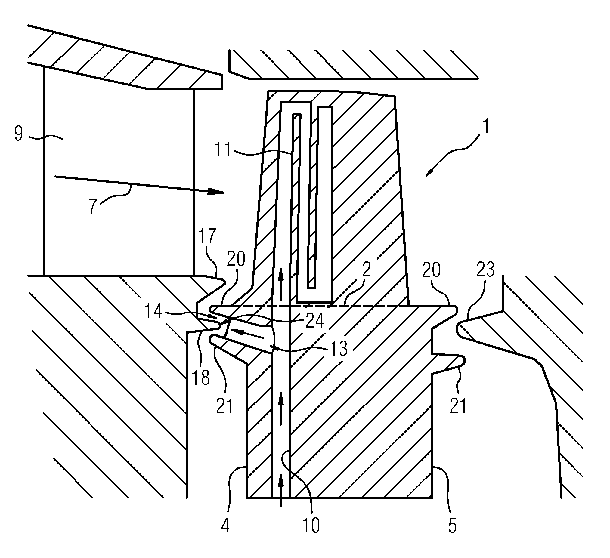
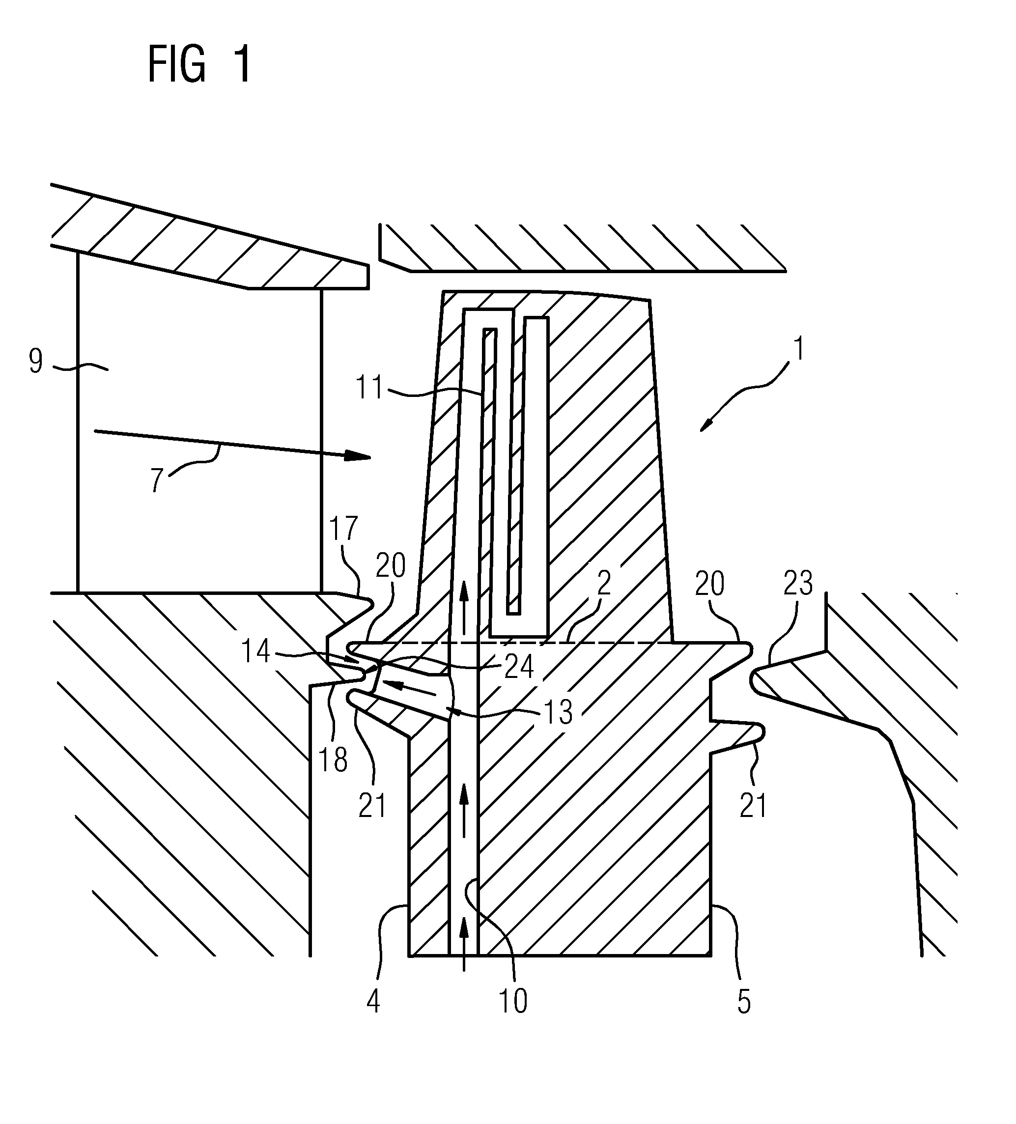
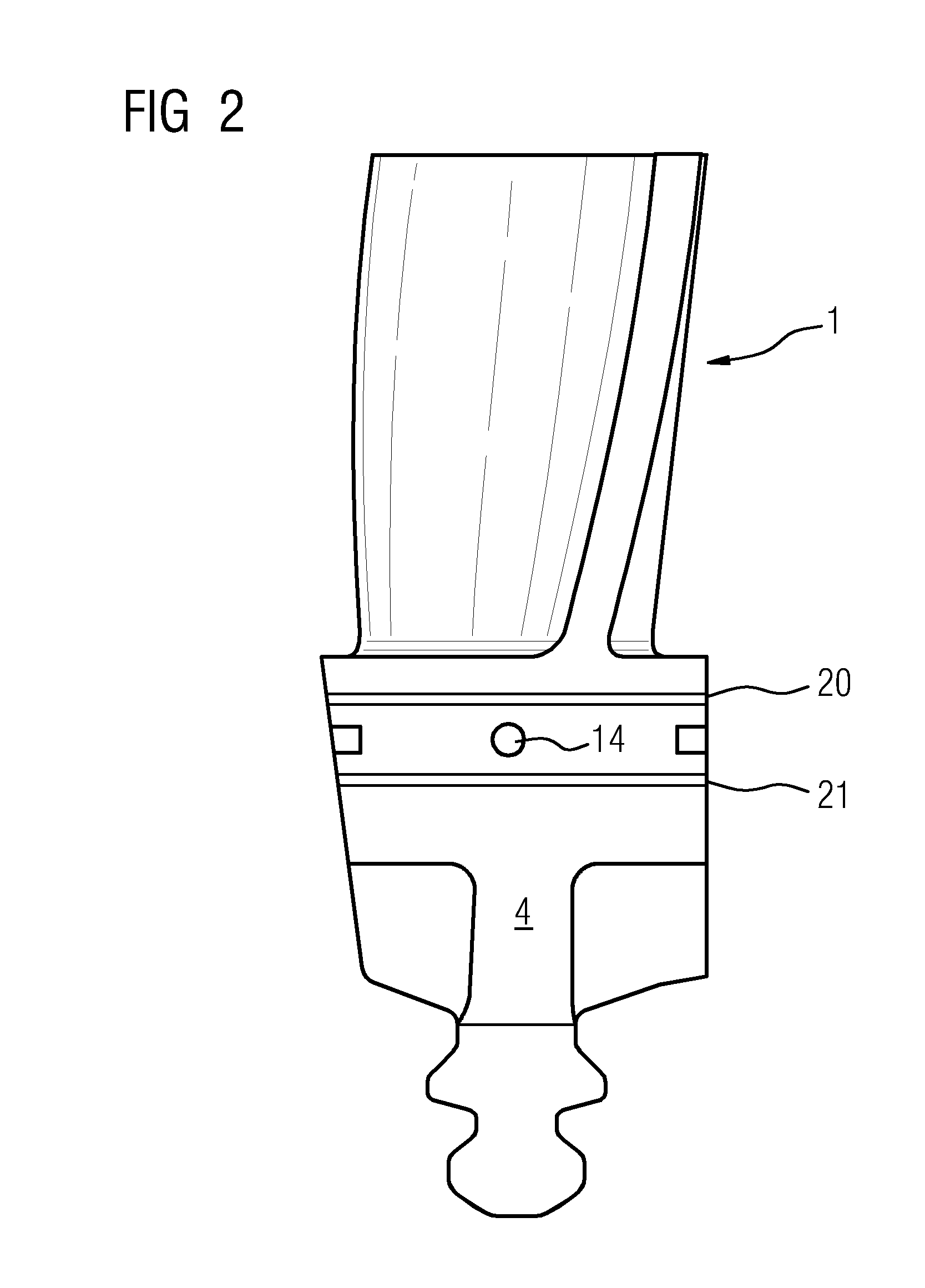
[0033]FIG. 1 shows in a partly sectional view parts of a stationary gas turbine. Especially, a blade 1 is shown. The blade 1 comprises a root portion. The root portion is the area under a dotted line 2 in FIG. 1. The root portion has four side walls, also referred to as sides, namely two narrow sides 4 and 5 and two broad sides, which are parallel to the plane of projection of FIG. 1.

[0034]Furthermore, the blade 1 comprises an airfoil which is depicted in FIG. 1 above the dotted line 2. The airfoil of blade 1 is arranged in a channel for a stream of hot gas 7—a main flow path of working fluid. The hot gas 7 is directed over the airfoil of the blade 1 to extract energy from the hot gas 7 for rotating a turbine rotor. The blade 1 is arranged on the turbine rotor (not shown).

[0035]A nozzle guide vane 9 (NGV) is arranged upstream of the airfoil of the blade 1. The nozzle guide vane 9 provides a constant and directed stream of hot gas 7 to rotating airfoils like the airfoil of blade 1. I...


PUM


Abstract

A blade for a turbomachine, for example a gas turbine, is provided. The blade is arranged on a turbine rotor of the gas turbine. The blade includes a root portion having two narrow sides and two broad sides, a cooling air supply passage in the root portion, and a cooling air bleed which is arranged in the root portion and is in fluid connection with the cooling air supply passage. The cooling air bleed includes a nozzle on one of the narrow sides of the root portion, wherein the nozzle is formed by a hole and wherein an axial direction of the hole is inclined upward between 92° and 135° with respect to a longitudinal direction of the blade.

Description

FIELD OF THE INVENTION[0001]The invention relates to a blade for a turbomachine, particularly a gas turbine, the blade particularly being arranged on a turbine rotor of the gas turbine. Furthermore, the invention relates to a turbomachine with a blade.BACKGROUND OF THE INVENTION[0002]Gas turbines known in the state of the art comprise a compressor, possibly divided in a low pressure compressor and a high pressure compressor. Furthermore, gas turbines have a combustor, where gas is mixed with compressed air. After exiting the combustor, the high energy gas stream then expands through the turbine, where energy is extracted to operate the compressor and produce mechanical work i.e. a torque.[0003]The pressure turbine is usually divided into a high pressure turbine and a low pressure turbine, wherein the high pressure turbine can include more than one stage as well as the low pressure turbine includes typically several stages. Each stage typically includes a rotor and a stator. The roto...

Claims


Application Information

Patent Timeline
IPC IPC(8): F01D25/12
CPCF05D2240/81F01D25/12F01D5/187F01D5/082F01D11/04F05D2260/201
Inventor DAVIS, ANTHONY
Owner SIEMENS AG
Learn More